Project Proposal

Video Lecture

Video, Slides

Description

The proposal outlines your project's motivation, design, requirements, ethics, and safety. The project proposal is an expansion on the information provided in the RFA. Use the following format (Word template):

  1. Introduction

    • Problem: In a few paragraphs introduce the problem and why it is important. Discuss briefly how it relates to societal concerns such as public health, safety and welfare as well as to global, cultural, social, environmental, and economic factors. Include any relevant references to justify the existence or importance of the problem.
    • Solution: One to two paragraphs describing the solution. Give a high-level idea of what your solution is, then delve into detail as to how it is implemented. You do not have to commit to a particular implementation at this point, but your description should be explicit and concrete.
    • Visual Aid: A pictorial representation of your project that puts your solution in context. Include other external systems relevant to your project (e.g. if your solution connects to a phone via Bluetooth, draw a dotted line between your device and the phone). Note that this is not a block diagram and should explain how the solution is used, not a breakdown of inner components.

      Sample visual aid for project which remaps GameCube buttons on the fly.

    • High-level requirements list: A list of three quantitative characteristics that this project must exhibit in order to solve the problem. Each high-level requirement must be stated in complete sentences and displayed as a bulleted list. Avoid mentioning "cost" as a high level requirement.
  2. Design
    • Block Diagram: Break your design down into blocks and assign these blocks into subsystems. Label voltages and data connections. Your microcontroller can live in multiple subsystems if you wish, as in the example below.

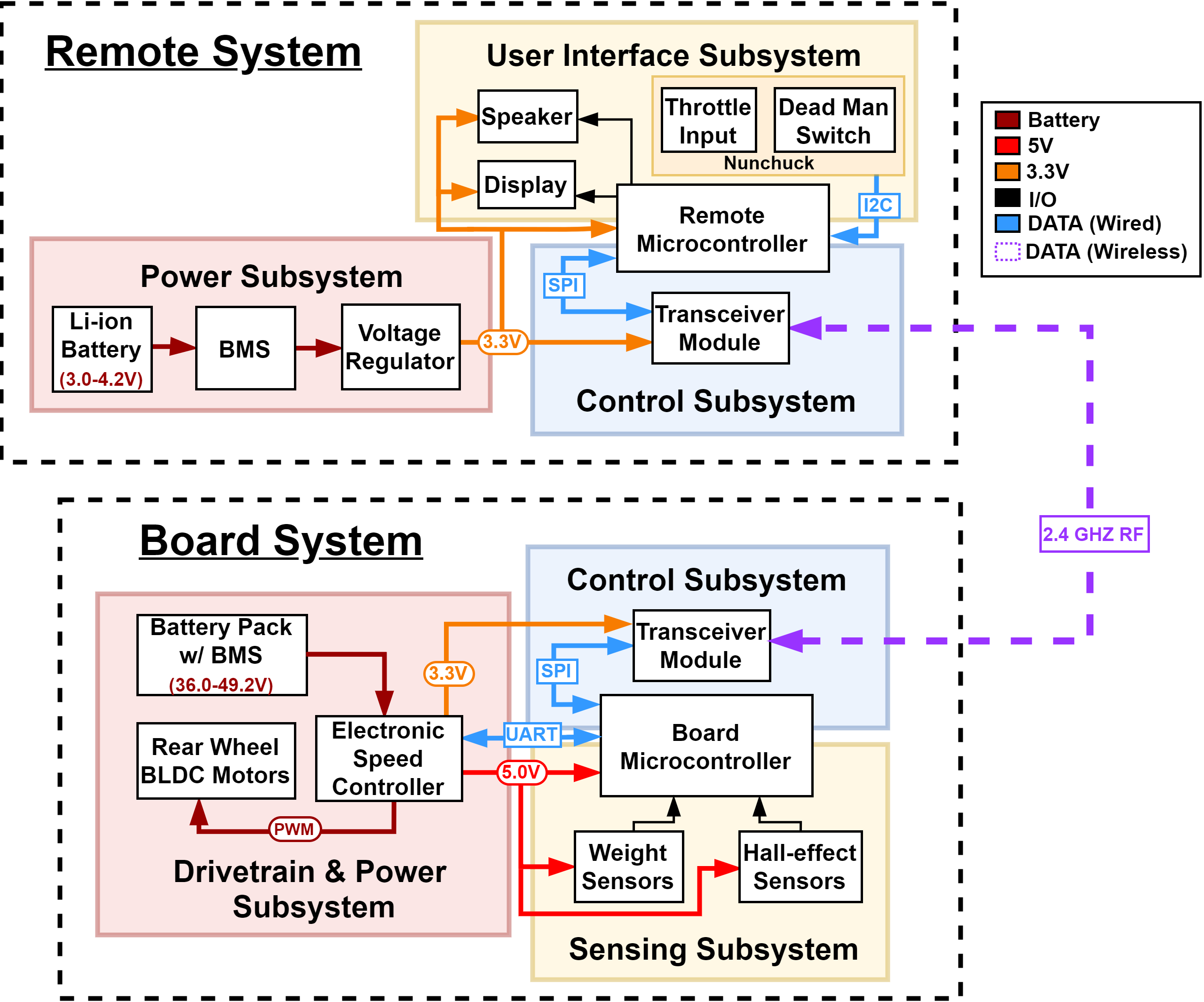
      Sample block diagram for electric longboard + remote

    • Subsystem Overview: A brief description of the function of each subsystem in the block diagram and explain how it connects with the other subsystems. Every subsystem in the block diagram should have its own paragraph.
    • Subsystem Requirements: For each subsystem in your block diagram, you should include a highly detailed block description. Each description must include a statement indicating how the block contributes to the overall design dictated by the high-level requirements. Any interfaces with other blocks must be defined clearly and quantitatively. Include a list of requirements where if any of these requirements were removed, the subsystem would fail to function. Good example: Power Subsystem must be able to supply at least 500mA to the rest of the system continuously at 5V +/- 0.1V.
    • Tolerance Analysis: Identify an aspect of your design that poses a risk to successful completion of the project. Demonstrate the feasibility of this component through mathematical analysis or simulation.
  3. Ethics, safety and societal impact
    As engineers you have ethical and professional responsibilities in making design decisions. Assess the ethical and safety issues relevant to your project. Consider both issues arising during the development of your project and those which could arise from the accidental or intentional misuse of your project. Specific ethical issues should be discussed in the context of the IEEE and/or ACM Code of Ethics. Cite, but do not copy the Codes. Explain how you will avoid ethical breaches. Cite and discuss relevant safety and regulatory standards as they apply to your project. Review state and federal regulations, industry standards, and campus policy. Identify potential safety concerns in your project. Discuss the impact of your engineering solution in relevant societal, economic, environmental, and global contexts.

Submission and Deadlines

The Project Proposal document should be uploaded to My Project on PACE in PDF format before the deadline listed on the Calendar.

ATTITUDE DETERMINATION AND CONTROL MODULE FOR UIUC NANOSATELLITES

Shamith Achanta, Rick Eason, Srikar Nalamalapu

Featured Project

Team Members:

- Rick Eason (reason2)

- Srikar Nalamalapu (svn3)

- Shamith Achanta (shamith2)

# Problem

The Aerospace Engineering department's Laboratory for Advanced Space Systems at Illinois (LASSI) develops nanosatellites for the University of Illinois. Their next-generation satellite architecture is currently in development, however the core bus does not contain an Attitude Determination and Control (ADCS) system.

In order for an ADCS system to be useful to LASSI, the system must be compliant with their modular spacecraft bus architecture.

# Solution

Design, build, and test an IlliniSat-0 spec compliant ADCS module. This requires being able to:

- Sense and process the Earth's weak magnetic field as it passes through the module.

- Sense and process the spacecraft body's <30 dps rotation rate.

- Execute control algorithms to command magnetorquer coil current drivers.

- Drive current through magnetorquer coils.

As well as being compliant to LASSI specification for:

- Mechanical design.

- Electrical power interfaces.

- Serial data interfaces.

- Material properties.

- Serial communications protocol.

# Solution Components

## Sensing

Using the Rohm BM1422AGMV 3-axis magnetometer we can accurately sense 0.042 microTesla per LSB, which gives very good overhead for sensing Earth's field. Furthermore, this sensor is designed for use in wearable electronics as a compass, so it also contains programable low-pass filters. This will reduce MCU processing load.

Using the Bosch BMI270 3-axis gyroscope we can accurately sense rotation rate at between ~16 and ~260 LSB per dps, which gives very good overhead to sense low-rate rotation of the spacecraft body. This sensor also contains a programable low-pass filter, which will help reduce MCU processing load.

Both sensors will communicate over I2C to the MCU.

## Serial Communications

The LASSI spec for this module requires the inclusion of the following serial communications processes:

- CAN-FD

- RS422

- Differential I2C

The CAN-FD interface is provided from the STM-32 MCU through a SN65HVD234-Q1 transceiver. It supports all CAN speeds and is used on all other devices on the CAN bus, providing increased reliability.

The RS422 interface is provided through GPIO from the STM-32 MCU and uses the TI THVD1451 transceiver. RS422 is a twisted-pair differential serial interface that provides high noise rejection and high data rates.

The Differential I2C is provided by a specialized transceiver from NXP, which allows I2C to be used reliably in high-noise and board-to-board situations. The device is the PCA9615.

I2C between the sensors and the MCU is provided by the GPIO on the MCU and does not require a transceiver.

## MCU

The MCU will be an STM32L552, exact variant and package is TBD due to parts availability. This MCU provides significant processing power, good GPIO, and excellent build and development tools. Firmware will be written in either C or Rust, depending on some initial testing.

We have access to debugging and flashing tools that are compatible with this MCU.

## Magnetics Coils and Constant Current Drivers

We are going to wind our own copper wire around coil mandrels to produce magnetorquers that are useful geometries for the device. A 3d printed mandrel will be designed and produced for each of the three coils. We do not believe this to be a significant risk of project failure because the geometries involved are extremely simple and the coil does not need to be extremely precise. Mounting of the coils to the board will be handled by 3d printed clips that we will design. The coils will be soldered into the board through plated through-holes.

Driving the inductors will be the MAX8560 500mA buck converter. This converter allows the MCU to toggle the activity of the individual coils separately through GPIO pins, as well as good soft-start characteristics for the large current draw of the coils.

## Board Design

This project requires significant work in the board layout phase. A 4-layer PCB is anticipated and due to LASSI compliance requirements the board outline, mounting hole placement, part keep-out zones, and a large stack-through connector (Samtec ERM/F-8) are already defined.

Unless constrained by part availability or required for other reasons, all parts will be SMD and will be selected for minimum footprint area.

# Criterion For Success

Success for our project will be broken into several parts:

- Electronics

- Firmware

- Compatibility

Compatibility success is the easiest to test. The device must be compatible with LASSI specifications for IlliniSat-0 modules. This is verifiable through mechanical measurement, board design review, and integration with other test articles.

Firmware success will be determined by meeting the following criteria:

- The capability to initialize, configure, and read accurate data from the IMU sensors. This is a test of I2C interfacing and will be tested using external test equipment in the LASSI lab. (We have approval to use and access to this equipment)

- The capability to control the output states of the magnetorquer coils. This is a test of GPIO interfacing in firmware.

- The capability to move through different control modes, including: IDLE, FAULT, DETUMBLE, SLEW, and TEST. This will be validated through debugger interfacing, as there is no visual indication system on this device to reduce power waste.

- The capability to self-test and to identify faults. This will be validated through debugger interfacing, as there is no visual indication system on this device to reduce power waste.

- The capability to communicate to other modules on the bus over CAN or RS422 using LASSI-compatible serial protocols. This will be validated through the use of external test equipment designed for IlliniSat-0 module testing.

**Note:** the development of the actual detumble and pointing algorithms that will be used in orbital flight fall outside the reasonable scope of electrical engineering as a field. We are explicitly designing this system such that an aerospace engineering team can develop control algorithms and drop them into our firmware stack for use.

Electronics success will be determined through the successful operation of the other criteria, if the board layout is faulty or a part was poorly selected, the system will not work as intended and will fail other tests. Electronics success will also be validated by measuring the current consumption of the device when operating. The device is required not to exceed 2 amps of total current draw from its dedicated power rail at 3.3 volts. This can be verified by observing the benchtop power supply used to run the device in the lab.