Project Proposal
Description
The proposal outlines your project's motivation, design, requirements, ethics, and safety. The project proposal is an expansion on the information provided in the RFA. Use the following format:
- Introduction
- Problem: One to two paragraphs detailing the problem statement. Include any relevant references to justify the existence or importance of the problem.
- Solution:
One to two paragraphs describing the solution. Give a high-level idea of
what your solution is, then delve into detail as tohow it is implemented. You do not have to commit to a particular implementation at this point, but your description should be explicit and concrete. - Visual Aid: A pictorial representation of your project that puts your solution in context. Include other external systems relevant to your project (e.g. if your solution connects to a phone via Bluetooth, draw a dotted line between your device and the phone). Note that this is not a block diagram and should explain how the solution is used, not a breakdown of inner components.

Sample visual aid for project which remaps GameCube buttons on the fly. - High-level requirements list: A list of three quantitative characteristics that this project must exhibit in order to solve the problem. Each high-level requirement must be stated in complete sentences and displayed as a bulleted list. Avoid mentioning "cost" as a high level requirement.
- Design
- Block Diagram: Break your design down into blocks and assign these blocks into subsystems. Label voltages and data connections. Your microcontroller can live in multiple subsystems if you wish, as in the example below.
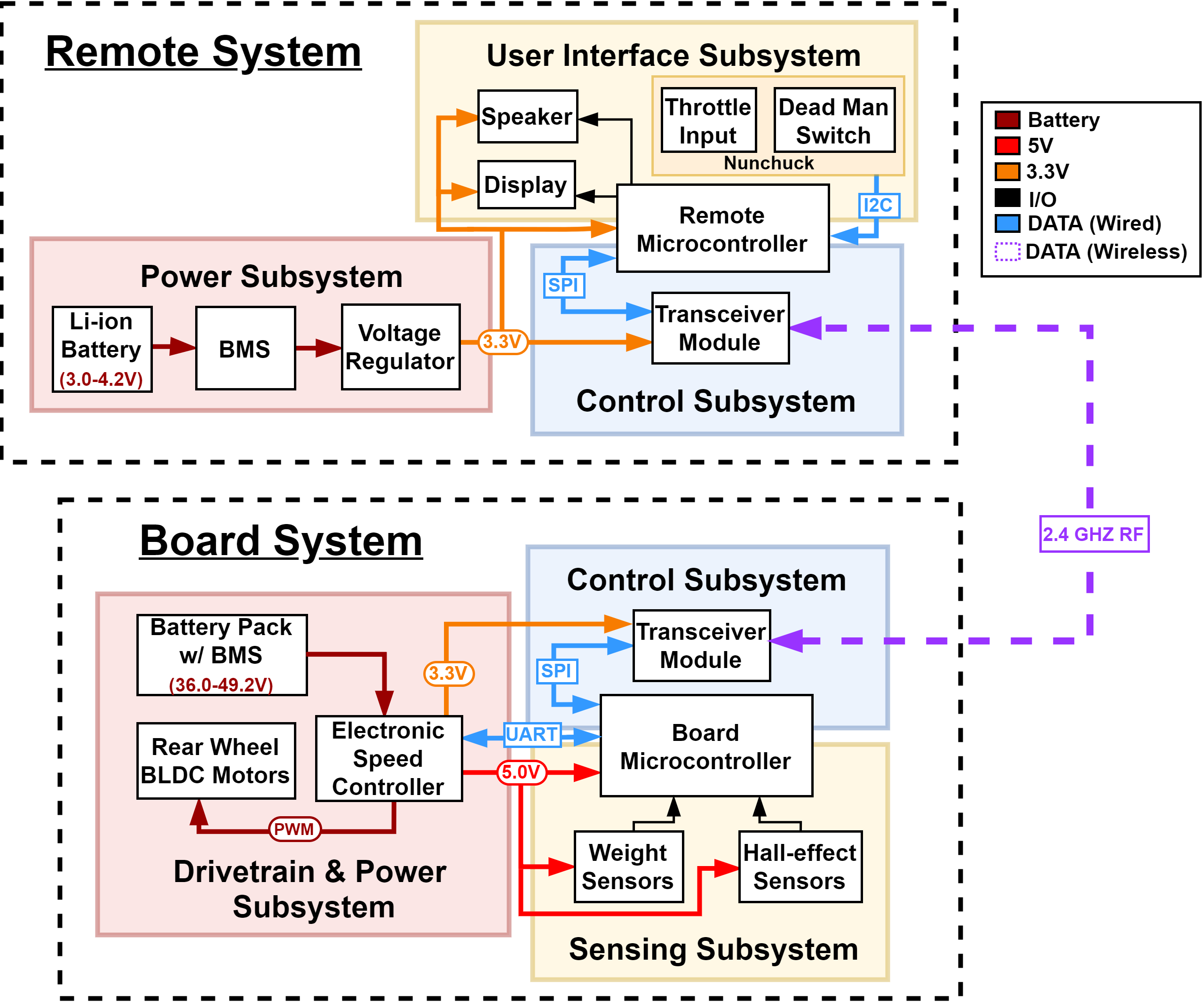
Sample block diagram for electric longboard + remote - Subsystem Overview: A brief description of the function of each subsystem in the block diagram and explain how it connects with the other subsystems. Every subsystem in the block diagram should have its own paragraph.
- Subsystem Requirements: For each subsystem in your block diagram, you should include a highly detailed block description. Each description must include a statement indicating how the block contributes to the overall design dictated by the high-level requirements. Any interfaces with other blocks must be defined clearly and quantitatively. Include a list of requirements where if any of these requirements were removed, the subsystem would fail to function. Good example: Power Subsystem must be able to supply at least 500mA to the rest of the system continuously at 5V +/- 0.1V.
- Tolerance Analysis: Identify an aspect of your design that poses a risk to successful completion of the project. Demonstrate the feasibility of this component through mathematical analysis or simulation.
- Block Diagram: Break your design down into blocks and assign these blocks into subsystems. Label voltages and data connections. Your microcontroller can live in multiple subsystems if you wish, as in the example below.
- Ethics and Safety
Assess the ethical and safety issues relevant to your project. Consider both issues arising during the development of your project and those which could arise from the accidental or intentional misuse of your project. Specific ethical issues should be discussed in the context of the IEEE and/or ACM Code of Ethics. Cite, but do not copy the Codes. Explain how you will avoid ethical breaches. Cite and discuss relevant safety and regulatory standards as they apply to your project. Review state and federal regulations, industry standards, and campus policy. Identify potential safety concerns in your project.
Formatting Guidelines
The formatting and writing style should be the same as that of the final report. Please see the Final Report Guidelines for details, or check out the Lecture slides on the topic. We recommend using a LaTeX template. You can find that on the Final Report page or here.
Submission and Deadlines
The Project Proposal document should be uploaded to My Project on PACE in PDF format before the deadline listed on the Calendar.
There are two deadlines on the Calendar. If you submit before the Early Deadline, your team will get 3 additional points of credit to be applied to your Proposal. This means that if your proposal would normally score an 18/25, you will instead receive a 21/25. It is highly recommended to complete your proposal by the early deadline for maximum points!