Soldering Assignment

Description

The soldering assignment is a basic soldering exercise that ensures all ECE 445/ME 470 students understand how to solder surface-mount and through-hole devices. Students will be provided with the necessary PCB, components, solder, flux, etc. The details of the soldering assignment can be found in the assignment sheet.

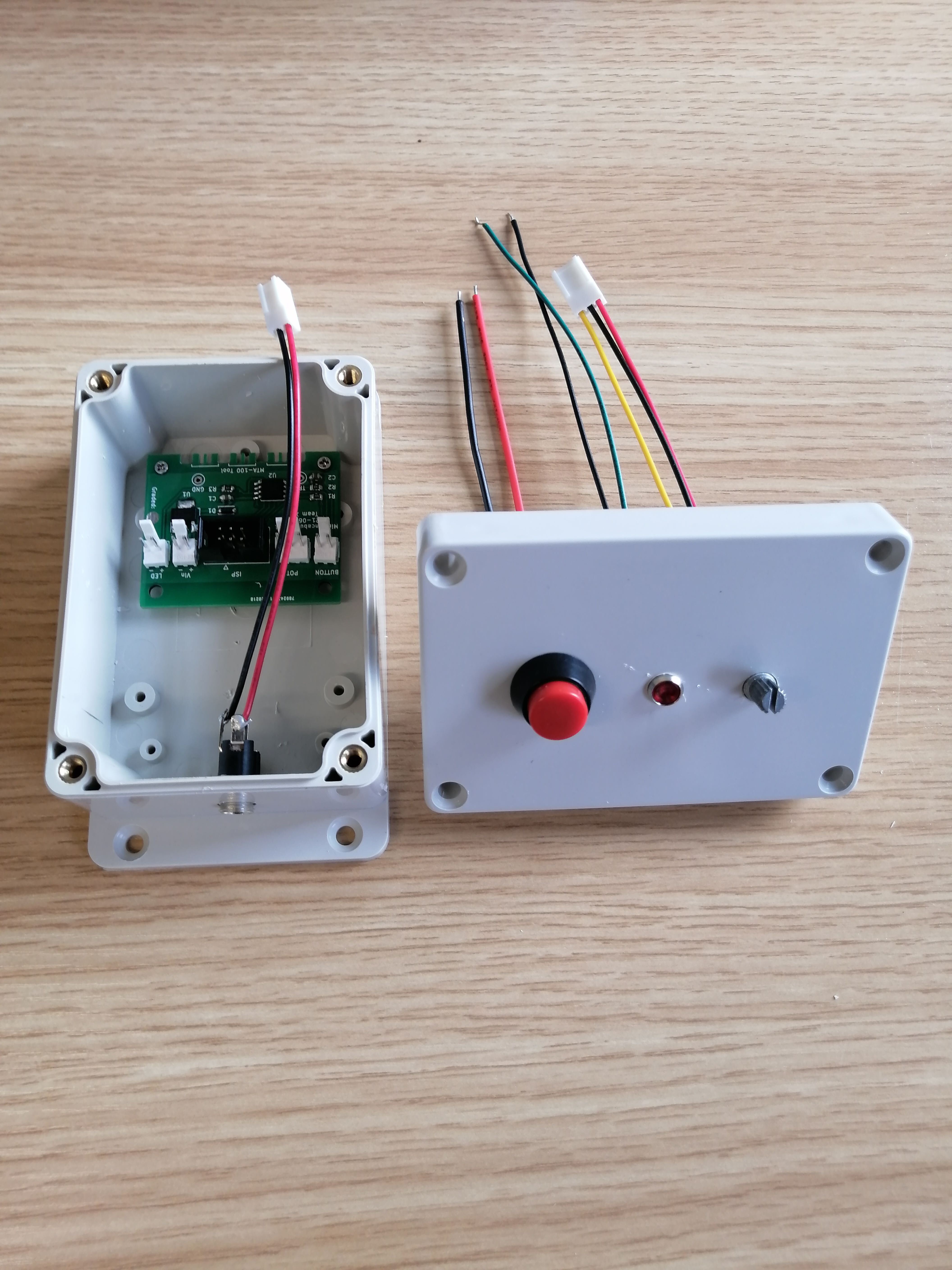
Your end product should look similar to the following. You will create a small device that blinks an LED at varying frequencies when the button is pressed, based on a potentiometer reading.

Soldering Assignment Image

Below is a series of soldering tutorials. The critical ingredient that you need to make your life easier while surface mount soldering (and through-hole too) is flux. There is liquid, water-soluble flux available in the lab. If you can't find it or don't know what it looks like, ask a lab staff member or TA for help.

Requirements and Grading

The soldering assignment is worth 10 points and is graded via inspection by a TA or Lab Staff member. Students are allowed to make as many attempts as necessary to complete the assignment.

Submission and Deadlines

The soldered PCB must be presented to a course staff member before the deadline listed on the Course Calendar.

Video Tutorials

Below are a few public video tutorials on Soldering. There is also a text description of how to solder on the soldering assignment doc linked above.

Through-hole (THT) and surface-mount (SMD) soldering tutorial:

Tutorial on using the various types of flux:

Tutorial on using wick to remove solder:

Tutorial on using a heat gun:

A Micro-Tribotester to Characterize the Wear Phenomenon

Shuren Li, Boyang Shen, Sirui Wang, Ze Wang

A Micro-Tribotester to Characterize the Wear Phenomenon

Featured Project

**Problem**

Many research efforts have been made to understand the complex wear mechanisms used to reduce wear in sliding systems and thus reduce industrial losses. To characterize the wear process, coefficient of friction needs to be measured “not only after completion of the wear test but also during the wear test to understand the transitional wear behavior that led to the final state”.(Penkov) In order to improve the effectiveness and efficiency of these research methods, it is necessary to improve the instrument used to characterize the wear phenomenon to better measure the friction coefficient of the material. Although the instrument can be applied on all solid samples, we will use silicon wafer coated with SiO2 as our specimen targeted object.

**Solution Overview**

The objective of the experiment is to evaluate the wear phenomenon of the sample during the sliding test so as to obtain the wear information of the material. We will design planar positioning and force sensing system to get the move and force information of our objects. To collect the data of vertical load and horizontal friction, 2 force sensors are mounted on linear rails to minimize the radial force and ensure that only the axial forces are collected. Then, the coefficient of friction can be calculated by equation:

![](https://courses.grainger.illinois.edu/ece445zjui/pace/getfile/18615)

And to determine the relationship between the coefficient of friction and the state of wear, we use a microscope to monitor the state of wear at a given location in the wear track and evaluate the wear process during each sliding cycle. In this way, we can investigate the wear transition processes with respect to the sliding distance then transport our data to a computer. Finally, we will design our data processing method in the computer to successfully obtain an acceptable result in the margin error.

**Solution Components**

1. Motion Platform: This subsystem includes a linear actuator that moves the sample in reciprocating motion along X-axis, a stationary counter surface that applies constant vertical load onto the sample, and another actuator that compresses the spring and provides a vertical load to the counter sample.

2. Specimen and Counter surface: We will test the wear and friction between the specimen and the counter surface during the sliding test. A 10 × 10 mm^2 silicon (Si) wafer coated with 50 nm thick SiO2 will be used as the specimen and a stainless-steel ball with a diameter of 1 mm was used as the counter surface.

3. Sensors: This subsystem includes two force sensors that measure the vertical load and horizontal friction. The Load Sensor should assemble along with the Z-axis actuator. To measure the friction without the effect of load, we assemble the Load Sensor and Friction Sensor sensor on the Linear Rails, as the photo attached shows. Since the sensors are strain gauges and only outputs, small changes in resistance, amplifiers, and ADC are needed to collect the signal and send converted data to the computer.

4. Data Processing: This subsystem includes acquiring raw data of load and friction on the computer, applying necessary filters to reduce noise and improve accuracy, and plotting the result that reflects the relationship between the sliding cycles and coefficient of friction for our sample.

![](https://courses.grainger.illinois.edu/ece445zjui/pace/getfile/18611)

**Criterion for Success**

1. Motion platform can perform precise reciprocation. The control system can effectively control the number and speed of reciprocating motion.

2. The acquisition unit can collect data effectively and can transfer the data that can be processed to the computer.

3. On a computer, the raw data can be processed into a readable graph based on algorithms set up. By analyzing the graph, the relationship between the data and the expected results can be correctly obtained.

**References**

Penkov OV, Khadem M, Nieto A, Kim T-H, Kim D-E. Design and Construction of a Micro-Tribotester for Precise In-Situ Wear Measurements. Micromachines. 2017; 8(4):103. https://doi.org/10.3390/mi8040103