ECE 486 Control Systems
Lecture 8
Open-Loop and Closed-Loop Control
Recall from last time, we talked about effects of extra zeros and stable poles of system transfer functions. We further introduce the concept of input-output stability and how to test system stability with Routh-Hurwitz criterion.
Today we will explore some basic properties and benefits of feedback control. We will see the difference between open-loop and closed-loop (feedback) control; examine the benefits of feedback in reference tracking and disturbance rejection; reduction of sensitivity to parameter variations; improvement of time response etc.
Two Basic Control Architectures
In general, we want a good control system to have the following three features,
- tracking a given reference;
- rejecting disturbances;
- meeting performance specs.
If we are going to consider two types of control schemes,
- the open-loop control as in Figure 1 and
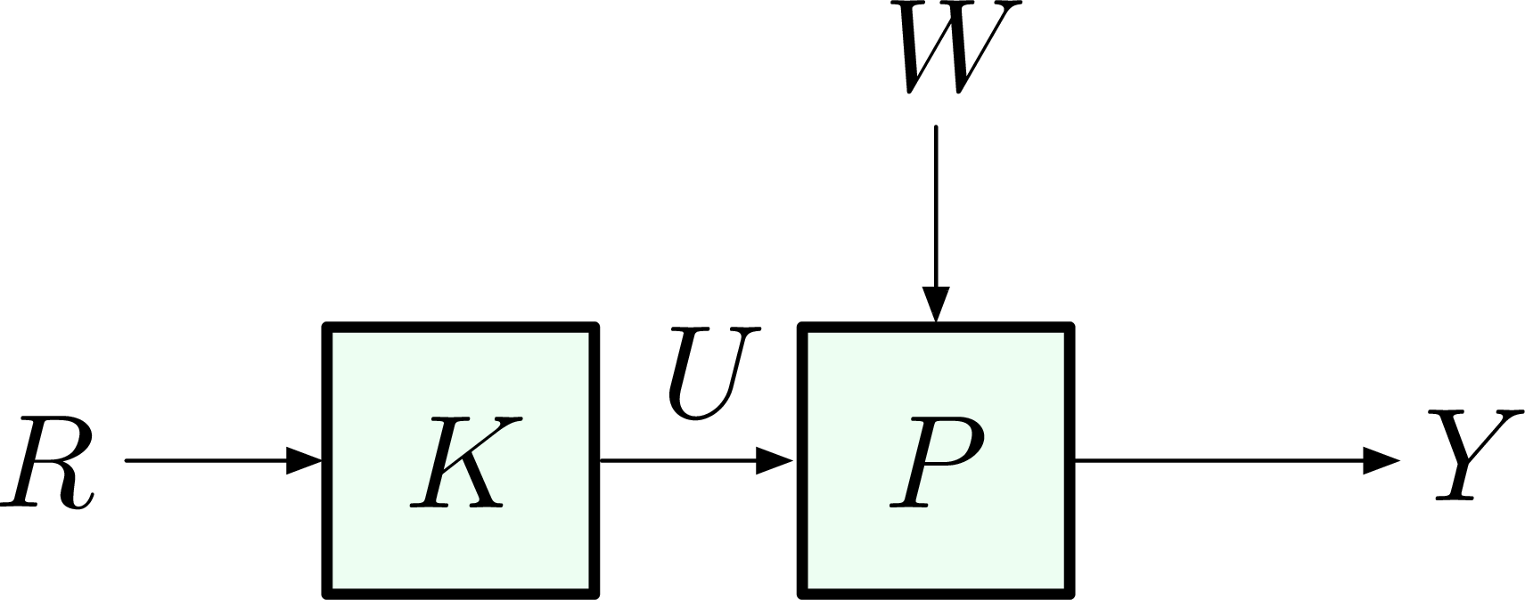
Figure 1: Open-loop control
- the feedback (closed-loop) control as in Figure 2.
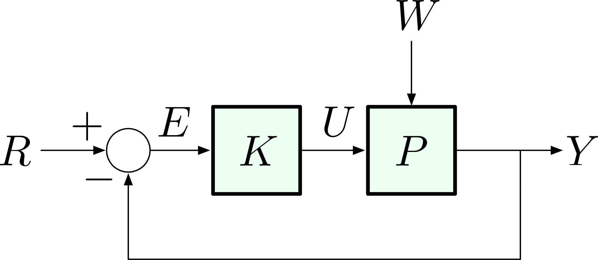
Figure 2: Closed-loop control
Correction: In both Figures 1 and 2, disturbance \(W\) shall be interpreted as input disturbance as we shall see below in the case study of a DC motor. On other occasions, we might have output disturbances. This subtlety was noted by \(D_1\) and \(D_2\) in Figure 9 of Lecture 1.
we shall see intuitively they differ by a feedback path. (Think of this difference as in cruise control.)
Note in both Figures 1 and 2, \(W\) is a disturbance; \(K\) is not necessarily a static gain.
When it comes to the three features, tracking, disturbance rejection and meeting specs, more specifically, in Figure 1, the open-loop control scheme is
- cheaper and easier to implement since no sensor is required for the feedback path and
- open-loop set-up does not destabilize the system.
For example, if both \(K\) and \(P\) have stable poles in the Open Left Half Plane, then \[ \dfrac{Y}{R} = KP \] is also stable since \[ \left\{ \text{poles of } KP \right\} = \left\{ \text{poles of } K \right\} \cup \left\{ \text{poles of } P \right\}. \]
On the other hand, the feedback control scheme in Figure 2 is
- more difficult or expensive to implement since it requires a sensor and an information path from controller to actuator on the feedback path and
- it may destabilize the system since
\[ \dfrac{Y}{R} = \frac{KP}{1+KP} \] has new poles, which may not be necessarily stable poles.
However, feedback control is the only way to stabilize an unstable plant. (This was the Wright brothers’ key insight.) Some of the benefits of feedback control include
- reducing steady-state error to disturbances;
- reducing steady-state sensitivity to model uncertainty (parameter variations);
- improving time response.
Case Study: DC Motor
Consider a DC motor assembly with input voltage \(v_{\rm a}(t)\), input load/disturbance torque \(\tau_{\rm e}(t)\). Denote angular speed of the motor \(\omega_{\rm m}(t)\) as the system output, then we have the system input output relationship,
\[ \tag{1} \label{d8_eq1} \Omega_{\rm m} = \frac{A}{\tau s + 1} V_{\rm a} + \frac{B}{\tau s + 1} T_{\rm e}, \] where \(\tau\) is the time constant of a first order transfer function and \(A,B\) are some system gains.
Figure 3 shows the diagram for Equation \eqref{d8_eq1}.
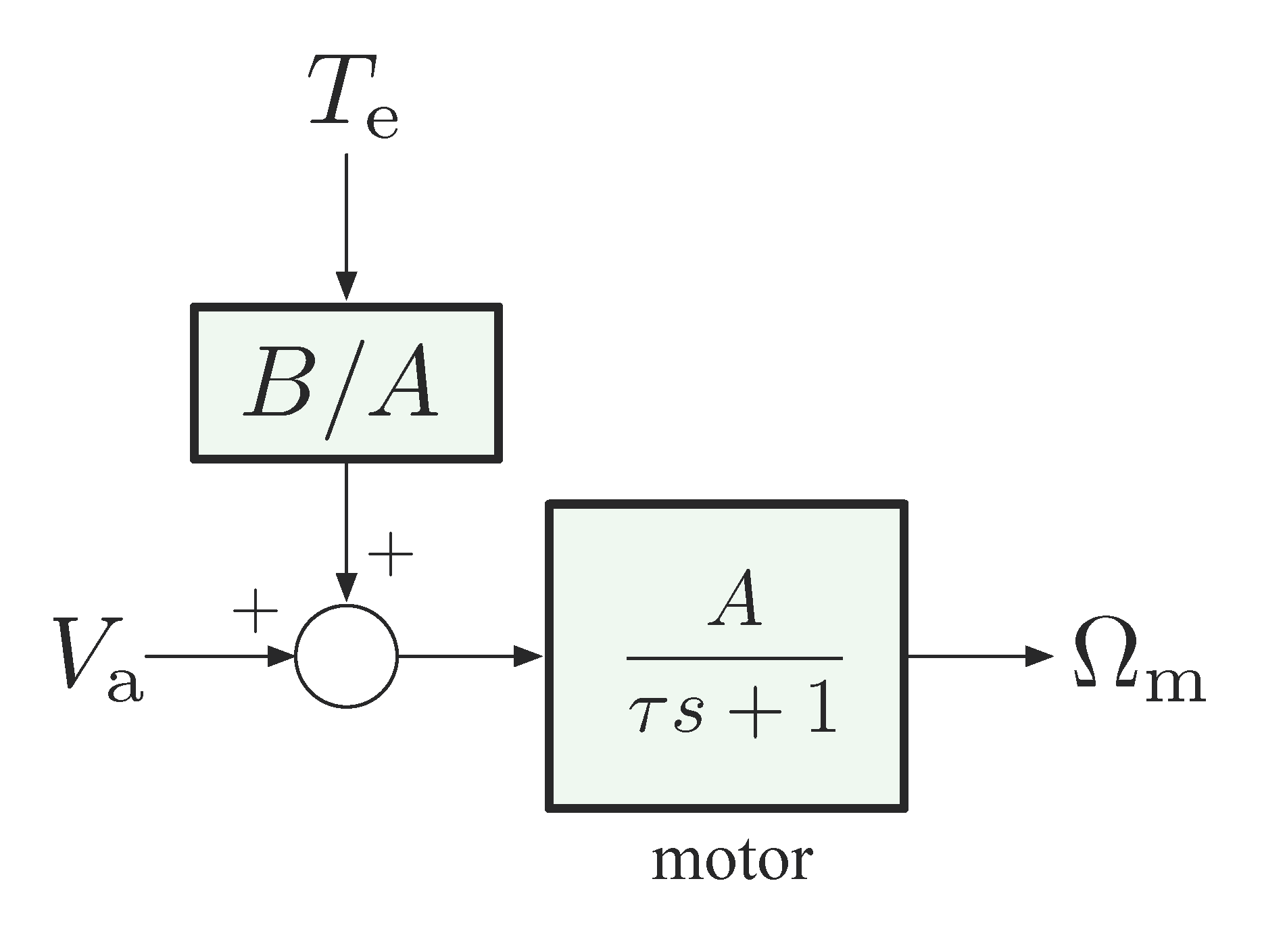
Figure 3: DC motor
Our objective is to have \(\Omega_{\rm m}\) approach and track a given reference \(\Omega_{\rm ref}\) in spite of disturbance \(T_{\rm e}\). To this end, we may consider both open-loop control and feedback (closed-loop ) control.
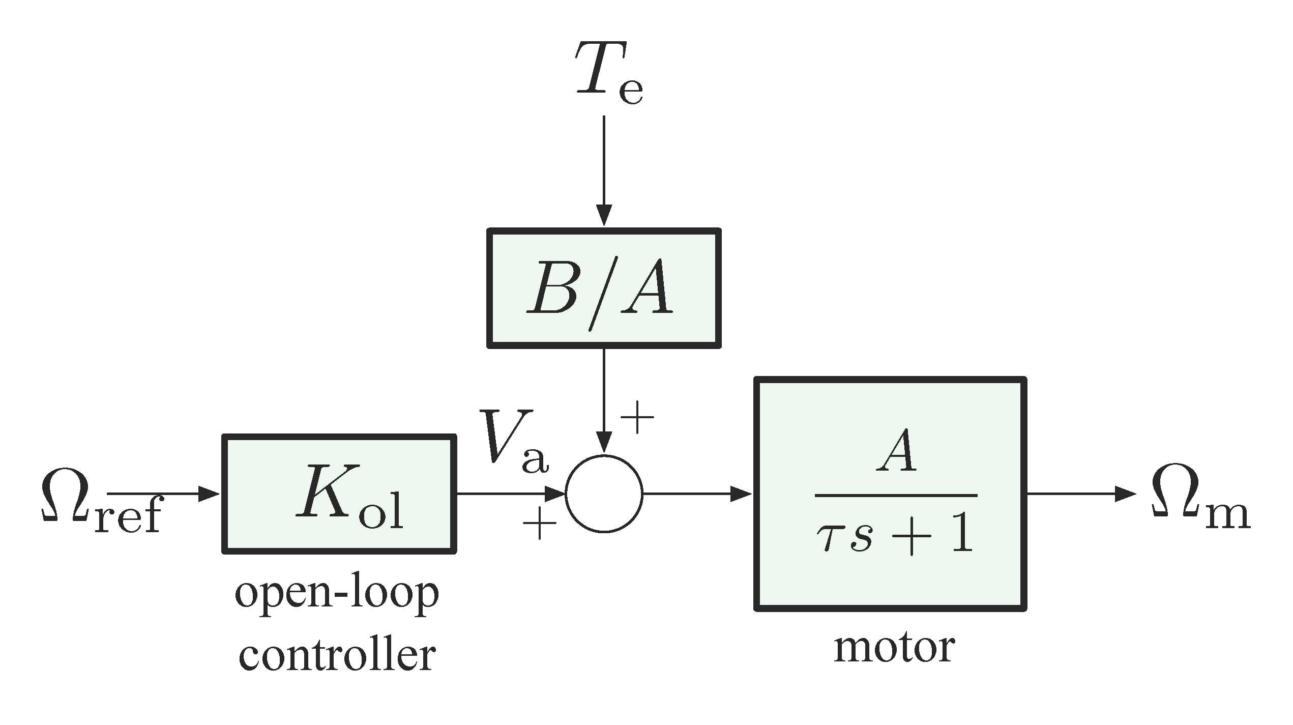
Figure 4: Open-loop control for DC motor
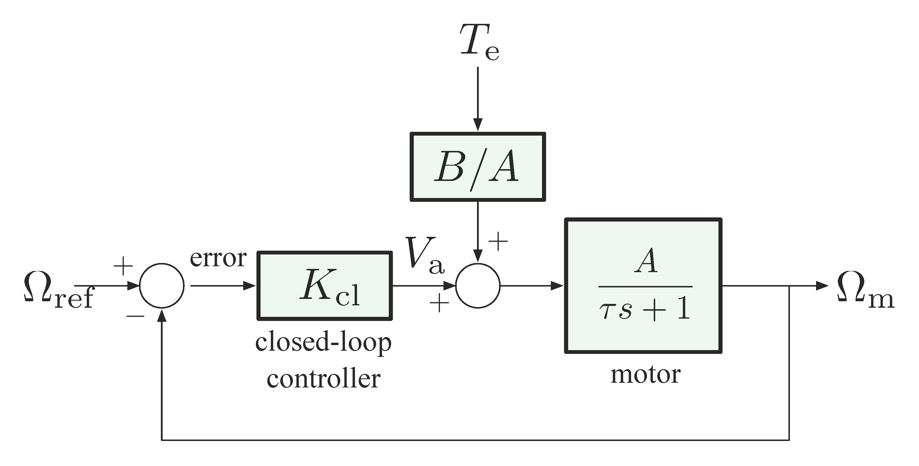
Figure 5: Feedback control for DC motor
Open-Loop Set-Up
If we use open-loop control as in Figure 4, first let’s investigate what happens to disturbance rejection.
Bear in mind our goal is to maintain \(\omega_{\rm m} = \omega_{\rm ref}\) in steady state in the presence of a constant disturbance. By open-loop, the controller receives no information about the disturbance \(\tau_{\rm e}\) since it gets no feedback signal from anywhere else. Therefore, the only input in open-loop set-up is reference \(\omega_{\rm ref}\).
A naïve attempt is that we can design for no disturbance, i.e., let \(\tau_{\rm e} = 0\), then see how the system works in general. With zero disturbance, the set-up in Figure 4 will be reduced to a simpler set-up as in Figure 6.
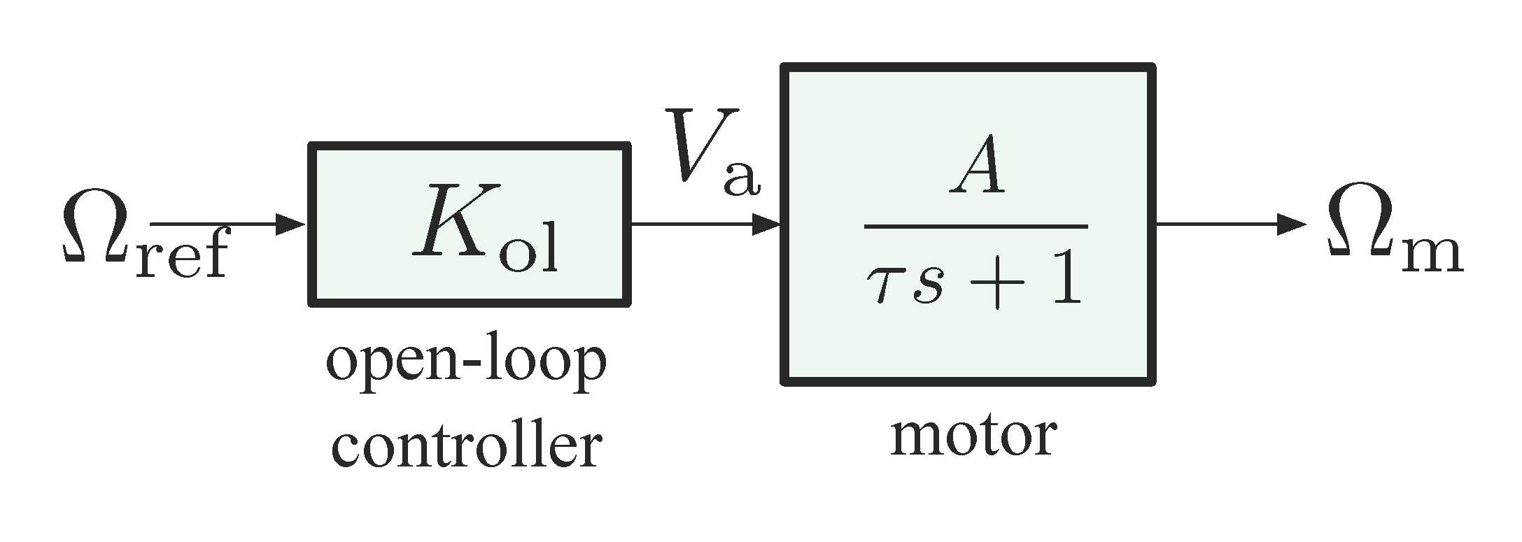
Figure 6: Open-loop control for DC motor (\(T_{\rm e} = 0\), no disturbance)
The motor transfer function in Figure 6 \[ \dfrac{A}{\tau s + 1}, \] has a stable pole at \(s =\frac{-1}{\tau}\). In order to have DC gain $ = 1$ (tracking) for transfer function \(\frac{\Omega_{\rm m}}{\Omega_{\rm ref}}\), by
\begin{align*} \Omega_{\rm m} &= \frac{A}{\tau s + 1}V_{\rm a} \\ &= \frac{K_{\rm ol}A}{\tau s + 1} \Omega_{\rm ref}, \end{align*}its numerator \(K_{\rm ol} A = 1\), i.e., \(K_{\rm ol} = \frac{1}A\). It follows we have perfect tracking when there is no disturbance by using such an open-loop controller \(K_{\rm ol} = \frac{1}A\),
\begin{align*} \omega_{\rm m}(\infty) &= \frac{1}{A} \cdot A \cdot \omega_{\rm ref} \\ &= \omega_{\rm ref}. \qquad \text{(for $T_{\rm e} = 0$)} \end{align*}Now, if nonzero disturbance \(T_{\rm e}\) is present, then the output speed
\begin{align*} \Omega_{\rm m} &= \underbrace{\frac{A}{\tau s + 1} \frac{1}{A}}_{\text{DC gain}=1} \Omega_{\rm ref} + \underbrace{\frac{B}{\tau s + 1}}_{\text{DC gain} = B} T_{\rm e}, \\ \implies \omega_{\rm m}(\infty) &= \underbrace{\omega_{\rm ref}}_{\text{step input}} + B\underbrace{\tau_{\rm e}}_{\text{step input}}.\tag{2} \label{d8_eq2} \end{align*}Equation \eqref{d8_eq2} says steady-state motor speed for an open-loop set-up with constant reference and constant disturbance is, the reference input with an offset determined by weighted disturbance input,
\[ \omega_{\rm m}(\infty) = \omega_{\rm ref} + B \tau_{\rm e}. \]
In the absence of disturbances, reference tracking is good; but disturbance rejection is pretty poor when disturbance kicks in. Steady-state error is determined by scaling factor \(B\) when nonzero disturbance contributes to system output, and we have no control over \(B\). Indeed, we cannot change the weight \(B\) of contribution to output by disturbance \(\tau_{\rm e}\) through any choice of controller \(K_{\rm ol}\), no matter how clever.
Feedback Control Set-Up
If we use closed-loop control as in Figure 5, let’s repeat the analysis what we did to open-loop set-up and see what happens to disturbance rejection in the case of feedback control.

Clear the denominator and solve for \(\Omega_{\rm m}\),
\begin{align*} (\tau s + 1)\Omega_{\rm m} &= A K_{\rm cl} \left(\Omega_{\rm ref} - \Omega_{\rm m}\right) + BT_{\rm e} \\ (\tau s + 1 + A K_{\rm cl})\Omega_{\rm m} &= A K_{\rm cl} \Omega_{\rm ref} + B T_{\rm e}, \\ \implies \Omega_{\rm m} &= \frac{AK_{\rm cl}}{\tau s + 1 + AK_{\rm cl}} \Omega_{\rm ref} + \frac{B}{\tau s + 1 + AK_{\rm cl}}T_{\rm e}. \tag{3} \label{d8_eq3} \end{align*}Question: All we want in Equation \eqref{d8_eq3} is writing output speed \(\Omega_{\rm m}\) in terms of reference input \(\Omega_{\rm ref}\) and disturbance (if any) \(T_{\rm e}\); can we apply our formula (forward gain)/(\(1\) + loop gain) to simplify the above process?
Hint: Since this is a linear system, and there are two different inputs \(\Omega_{\rm ref}\) and \(T_{\rm e}\), we can consider the contribution by one of them to the output at a time. \[ \Omega_{\rm m} = \left[\frac{\Omega_{\rm m}}{\Omega_{\rm ref}} \right] \Omega_{\rm ref} + \left[\frac{\Omega_{\rm m}}{T_{\rm e}} \right] T_{\rm e}. \] To compute the first transfer function \(\frac{\Omega_{\rm m}}{\Omega_{\rm ref}}\), set \(T_{\rm e} = 0\) in Figure 5, simplify the diagram and reshape the loop if necessary, figure out which signal is input and which signal is output. Apply the formula (forward gain)/(\(1\) + loop gain) to the standard feedback connection after reshaping.
Similar computation can be carried out when the second transfer function \(\frac{\Omega_{\rm m}}{T_{\rm e}}\) is concerned.
Provided all transfer functions are strictly stable, we have
\begin{align*} \Omega_{\rm m} = \underbrace{\frac{AK_{\rm cl}}{\tau s + 1 + AK_{\rm cl}}}_{\text{DC gain}= \frac{AK_{\rm cl}}{1+AK_{\rm cl}}} \Omega_{\rm ref} + \underbrace{\frac{B}{\tau s + 1 + AK_{\rm cl}}}_{\text{DC gain} = \frac{B}{1+AK_{\rm cl}}}T_{\rm e}. \end{align*}Assuming that the reference \(\omega_{\rm ref}\) and the disturbance \(\tau_{\rm e}\) are constant inputs, if we apply Final Value Theorem, we get
\begin{align*} \omega_{\rm m}(\infty) = \frac{AK_{\rm cl}}{1+AK_{\rm cl}}\omega_{\rm ref} + \frac{B}{1+AK_{\rm cl}}\tau_{\rm e}. \end{align*}In conclusion,
- even \(\dfrac{AK_{\rm cl}}{1+AK_{\rm cl}} \neq 1\), meaning tracking cannot be “perfect”, but this number can be brought arbitrarily close to \(1\) when \(K_{\rm cl} \to \infty\). Thus, steady-state tracking is good with high control gain \(K_{\rm cl}\), but never quite as good as in open-loop case, where tracking is perfect when there is no disturbance;
- weight of contribution of disturbance input \(\dfrac{B}{1+AK_{\rm cl}}\) is small (arbitrarily close to \(0\)) when \(K_{\rm cl}\) is large. Thus, feedback control set-up is much better than open-loop control when it comes to disturbance rejection.
Sensitivity to Parameter Variations
The sensitivity analysis we are talking about here is due to H. Bode. Consider again our DC motor model with no disturbance


In the “nominal” situation, we have the motor with \(\text{DC gain} = A\), and the overall transfer function, either open- or closed-loop, has some other DC gain (call it \(T\)).
Now suppose that, due to modeling error, changes happen in operating conditions, etc., accordingly the motor gain changes,
\[ A \mapsto A + \underbrace{\delta A}_{\text{small} \atop \text{perturbation}}. \]
This will cause a perturbation in the overall DC gain, \[ T \mapsto T + \delta T. \] From calculus, we know to the first order, \(\delta T \approx \frac{\d T}{\d A}\delta A\) if we treat overall gain \(T\) as a function of \(A\).
\[ A \mapsto A + \delta A \implies T \mapsto T + \delta T. \] It says a small perturbation in system gain \(A\) has been propagated, resulting in a perturbation in overall DC gain \(T\).
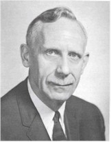
Figure 10: Hendrik Wade Bode, 1905–1982
To characterize this parameter variation, Bode introduced sensitivity
\begin{align*} {\cal S} &\triangleq \frac{\delta T/T}{\delta A/A}\\ &= \text{relative error} \\ &= \frac{\text{normalized (percentage) error in $T$}}{\text{normalized (percentage) error in $A$}}. \end{align*}Let’s compute sensitivity \({\cal S}\) for our DC motor control example, both open- and closed-loop.
Sensitivity for open-loop set-up: The nominal overall gain
\begin{align*} T_{\rm ol} &= K_{\rm ol} A \\ &= \frac{1}{A} A = 1. \end{align*}When perturbation in \(A\) happens,
\begin{align*} A &\mapsto A + \delta A, \\ \implies T_{\rm ol} &\mapsto K_{\rm ol} (A + \delta A) = \underbrace{\frac{1}{A}}_{\text{design} \atop \text{choice}} \left(A + \delta A\right) = \underbrace{1}_{T_{\rm ol}} + \underbrace{\frac{\delta A}{A}}_{\delta T_{\rm ol}}. \end{align*}Therefore sensitivity in the case of open-loop control is
\begin{align*} {\cal S}_{\rm ol} &= \dfrac{\delta T_{\rm ol}/T_{\rm ol}}{\delta A_{\rm ol}/A_{\rm ol}} \\ &= \dfrac{\delta A/A}{\delta A/A} \\ &= 1. \end{align*}Since sensitivity \({\cal S_{\rm ol}}\) is \(1\), as a quick example, a $5$% error in \(A\) will cause a $5$% error in \(T_{\rm ol}\).
Sensitivity for closed-loop set-up: The nominal overall gain
\[ T_{\rm cl} = \dfrac{AK_{\rm cl}}{1+AK_{\rm cl}}. \]
When perturbation in \(A\) happens,
\begin{align*} A &\mapsto A + \delta A, \\ \implies T_{\rm cl} &\mapsto T_{\rm cl} + \delta T_{\rm cl}, \tag{4} \label{d8_eq4} \end{align*}By Taylor expansion,
\begin{align*} T(A + \delta A) = T(A) + \frac{\d T}{\d A}(A)\delta A + \text{higher-order terms}, \end{align*}Abuse of Notation: \(T(A + \delta A)\) above is not multiplication of \(T\) and \(A + \delta A\); the parentheses were meant to denote \(T\) as a function evaluated at \(A + \delta A\). Similarly in \(\frac{\d T}{\d A}(A)\), the derivative \(\frac{\d T}{\d A}\) was evaluated at \(A\).
therefore substitute
\begin{align*} \frac{\d T_{\rm cl}}{\d A} &= \frac{K_{\rm cl}}{1+AK_{\rm cl}} - \frac{AK^2_{\rm cl}}{(1+AK_{\rm cl})^2} \\ &= \frac{K_{\rm cl}}{(1+AK_{\rm cl})^2}, \\ \end{align*}into Equation \eqref{d8_eq4}, we get \[ \delta T_{\rm cl} = \frac{K_{\rm cl}}{(1+AK_{\rm cl})^2} \delta A. \]
Finally, the sensitivity
\begin{align*} {\cal S}_{\rm cl} &= \dfrac{\delta T_{\rm cl}/T_{\rm cl}}{\delta A/A} \\ &=\frac{\frac{\frac{K_{\rm cl}}{(1+AK_{\rm cl})^2} \delta A}{\frac{AK_{\rm cl}}{1+AK_{\rm cl}}}}{\delta A/A} \\ &=\frac{\frac{1}{1+AK_{\rm cl}} \delta A/A}{\delta A/A} \\ &=\dfrac{1}{1+AK_{\rm cl}}. \end{align*}With high control gain \(K_{\rm cl}\) in closed-loop, we get smaller relative error due to parameter variations in the plant model since \({\cal S}_{\rm cl} \ll 1\) for large \(K_{\rm cl}\).
Time Response
For the rest of this lecture, we assume no disturbance \(\tau_{\rm e} = 0\).
So far, we have focused on DC gain only (steady-state response). What about transient response?
In the case of open-loop control,
\[ \frac{\Omega_{\rm m}}{\Omega_{\rm ref}} = \dfrac{AK_{\rm ol}}{\tau s + 1}. \]
The transfer function \(\frac{\Omega_{\rm m}}{\Omega_{\rm ref}}\) has a pole at \(s=-\dfrac{1}{\tau}\), i.e., in time domain, its transient response is associated with exponential \(e^{-t/\tau}\).
Here \(\tau\) is the time constant: the time it takes the system response to decay to \(1/e\) of its starting value.
In the open-loop case, larger time constant means faster convergence to steady state. This is not affected by the choice of \(K_{\rm ol}\) in any way!
In the case of closed-loop control,
\[ \frac{\Omega_{\rm m}}{\Omega_{\rm ref}} = \dfrac{AK_{\rm cl}}{\tau s + 1 + AK_{\rm cl}}. \]
The transfer function \(\frac{\Omega_{\rm m}}{\Omega_{\rm ref}}\) has a closed-loop pole at \(s= - \frac{1}{\tau}\left(1+AK_{\rm cl}\right)\). So the closed-loop pole can be moved around via feedback control \(K_{\rm cl}\).
The transient response is associated with \(e^{-\frac{1+AK_{\rm cl}}{\tau}t}\), with \[ \text{time constant} = \frac{\tau}{1+AK_{\rm cl}}. \]
If closed-loop control gain \(K_{\rm cl}\) is large, we have a much smaller time constant, i.e., time response converges faster to steady-state.
Summary: Feedback control can
- reduce steady-state error to disturbances;
- reduce steady-state sensitivity to model uncertainty (parameter variations);
- improve time response.
But note high-gain feedback only works well for first order systems in general; for higher-order systems, it will typically cause underdamping and instability.