Group Member: Shomik Chatterjee (shomikc2, ECE 110)
Purpose: This project seeks to create some device that is capable of detecting objects through/inside walls/barriers using microwave imaging. An 'extra' objective would be to replace the bulkier parts (VNA, computer, etc.) with custom, compact devices to allow for portability.
But Why? Microwave imaging is useful today in detecting potential breast cancer, detecting anomalies in structures (i.e. internal breaks/cracks in bridge trusses), or for detecting objects hidden inside/behind a wall.
Research: Vector Network Analyzers, also known as VNA's, can be used to measure the scattering parameters of microwaves reflected off surfaces. By attaching a microstrip antenna to a rotating mount and using stepper motors to rotate the mount and antenna, the VNA will be able to record the s-parameters with the antenna in different orientations relative to the object we are attempting to detect. This data will be fed into the computer, which will use a program to analyze the data and determine the existence, position, and size of an object behind a wall.
Parts List:
Tektronix TTR506A – Vector Network Analyzer (it's normally $12,300-13,000 but I was able to borrow one for the duration of this semester for this project)
Stepper Motor 17HD40005H-22B ZYLTECH – Stepper motor (10$ on ZYLTECH's website)
SNA-male to N-male adapter (SM4267) (44$ from Fairview Microwave)
TB6600 4A 9-42V Stepper Motor Driver (12$ off Amazon)
Arduino ONE – micro-controller (22$ off Amazon)
2.8 GHz microstrip antenna (borrowed antenna)
Antenna Mount (custom 3-d printed mount)
HP Pavilion Laptop ($1,000 approx.)
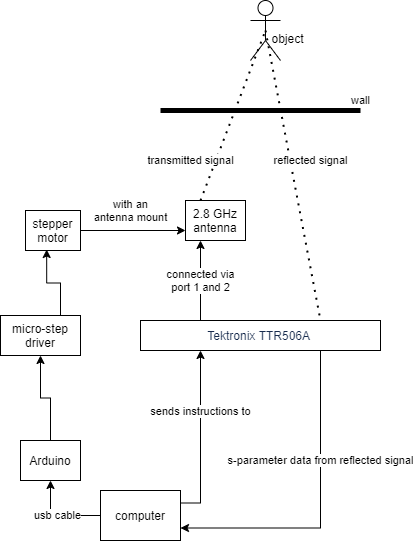
Block Diagram:
(Fig. 1 - Preliminary block diagram for the system)
How I will approach this:
-setting up the VNA so that it properly records both the transmitted wave and the reflected wave from the antenna - completed on 10/23/2020
-setting up LabView Vector-Vu on my computer and recording data on my computer - completed on 10/23/2020
-coding the program that takes the data from the VNA and produces a meaningful result - still working, 11/19/2020
-setting up the rotating antenna system - completed 11/19/2020
-making sure the entire system works, integrating the rotating antenna mount and the data collection
(things to do if time permits) - none of these will be possible as of 11/19/2020
-custom microstrip antenna for this project
-making a custom VNA instead of using a borrowed Tektronix VNA
-using a Raspberry Pi instead of my laptop in order to make the system portable
Progress Reports:
10/23/2020:
THINGS ACCOMPLISHED:
Connected antenna to computer through VNA.
Downloaded PyVISA and all related backends/prerequisites.
Tested the 'detection' abilities of the VNA/antenna system by placing various objects in front of it. Does not seem to be capable of detecting anything – possible reasons:
- VNA needs to be calibrated
- Objects need to be further away
- Antenna is faulty
THINGS TO DO:
Connect Python script with Vector-Vu (virtual instrument, connected to VNA)
Begin work on stepper motor circuit
Finish filling out library of commands for python script
NOTES:
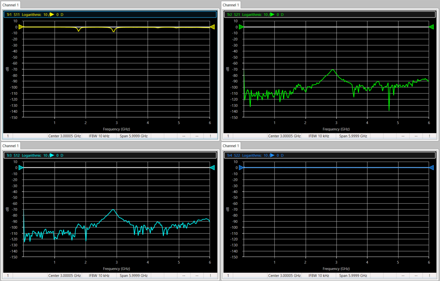
Antenna was rated at 2.8 GHz - VNA confirms this through s-parameter measurements.
(Fig. 2 - S-parameter measurements when antenna is connected to VNA at port 1. The two small dips in S11 correspond to the relative peaks in S21 and S12, occurring at about 1.7 GHz and 2.8 GHz)
VNA is very temperamental - if VNA does not properly connect with computer, turn the VNA off and on again until it does. Computer may also need to be restarted
VNA itself cannot communicate using VISA - if an external script is going to be used to automate data collection, then the script needs to communicate with the Vector-Vu program, not the device itself.
11/19/2020:
VNA now works consistently.
Original antenna was faulty, New antennas used for project:
Monopole 1.8 GHz Wi-Fi antenna x2
Monopole 1.6 GHz Wi-Fi antenna x2
Centurion BlueChip CAF95901 antenna x2
Various patch antennas
The s-parameters for each antenna + an SNA-male to N-male adapter (SM4267) have been recorded here (note: only one of the 1.6 GHz Wi-fi antenna was tested).
Using another adapter (SNA female to N-male) and various cables, testing pairs of antennae seems to produce a better result for object detection than one antenna.
Circuit involving Arduino Uno, stepper motor driver, and stepper motor has been completed.
Next step is to extensively test detection capabilities of two antennae.
Help Received:
I would like to thank Stephen Young and Benjamin Bissen for sending me the references for this project and supplying some of the parts and some of the code for this project.
References:
H. Aniktar, "A Portable Through-Wall Microwave Imaging System," ACES JOURNAL, Vol. 35, No. 1, January 2020
A. M. Hassan and M. El-Shenawee, "Review of Electromagnetic Techniques for Breast Cancer Detection," IEEE REVIEWS IN BIOMEDICAL ENGINEERING, VOL. 4, 2011

