Member:Bug Lee (cl37), Jialiang Xu(jx17), Rushill Shah(rushill2)
Introduction:
- Statement of purpose
During winter season, we can easily see a house with LEDs that synchronized to radio music. Our group intend to design circuit that act in similar way where it would react to certain sound signals. Unlike LED houses, we plan to work without help of Arduino or other pre-built hardware or software, rather working from the bottom and dive deeper on the functions of each chip and circuit component. - Background Research
Our goal is to apply and learn more about basic signal processing. For this project we will focus on one of the most basic signal: sound, particularly on volume and frequency of sound. Signal processing is a foundation to many subject where even our own body need to process electrical signal from the brain to function. Although every signal is different and unique, we believe that all signal have two main things to consider: amplitude and frequency. Thus, if we learn how to process sound signal now, it would open up much bigger door for us in future projects.
2.Design Details
- Block Diagram / Flow Chart
- System Overview
Input
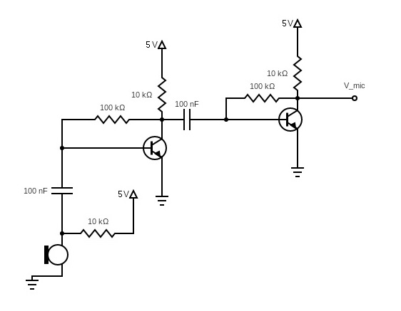
We use electret microphone that was provided from ece110 kit. Because signal from microphone was less than millivolt, amplification was needed. By connecting firstly amplified signal to second BJT's gate, we manage to amplify signal up to 5v, which is sufficient for our purpose.
Filtering process
- Implementing filters for our circuit brought many challenges since no one in our group were familiarize with it.
- Only recently I learned that each filter need buffer, so filters do not interfere with each other.
- Here are the 3 methods that we tried so far:
Method 1: converting to square wave and using capacitor
In this method, high frequency would output higher voltage than low frequency because capacitor do not get fully discharge.
Disadvantage of Method 1 was that circuit become massive quickly. TA dis-recommended due to possible inaccuracy in output.
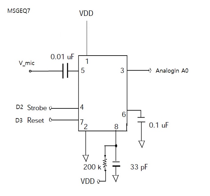
Method 2: MSGEQ7 + Arduino
Although our group originally didn't plan to use Arduino for any part of our circuit, we decided to borrow their hand until we learn about filtering.
MSGEQ7 contain bandpass filters inside the chips, which made our circuit much simpler. However, it also acts as disadvantage since values are fix.
Nonetheless, MSGEQ7 was useful tool where we successfully tested few outputs.
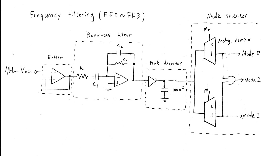
Method 3: Buffer + bandpass filter(op amp) + peak detector
This is the method that we are currently working on.
Our project is design to deal with 4 different frequency bands. Use of components are the same beside the R1, R2, C1, and C2. Those value will vary depend on set frequency band.
We intend to implement mode selector where we are currently working with analog demultiplexer.
Output
In our project, there is 3 different output mode depend on the external input(m0, m1) from user.
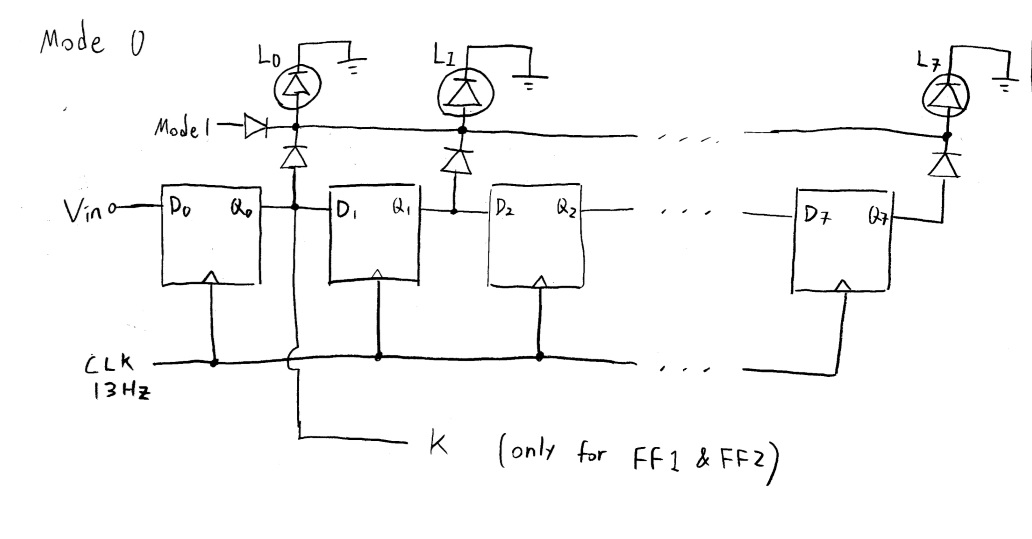
Mode0. LED rain drop
- We utilized shift register to generate rain drop effect. There are few thing to consider:
- 1.LEDs are also connected to Mode 1 circuit, which is discuss in the next section.
- 2.Mode0 that connected to FF1 & FF2 have additional output K, which will be use as an input for Mode 2.
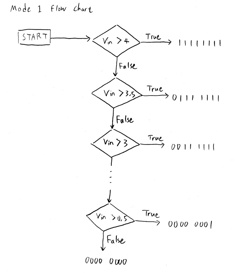
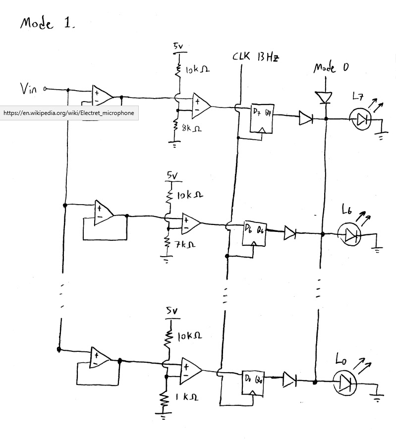
Mode1. spectrum analyzer
- In this mode, our goal is to generate graphical representation of each signal's amplitude.
- Note that output bit have direct connection to LEDs. For instance 11111111 correspond to 8 LEDs turning on, where no LEDs are turn on 00000000.
- Each branch is consist of buffer, voltage comparator, and D-flip flop.
- Mode1 that connected to FF1 & FF2 have additional output A, which will be use as a input for Mode 2.
Mode2. LED lip sync
- Although we lost many part of information from original signal through filtering and processing, there are still useful information that can be a extract.
- In the Mode2, we will use amplitude information from Mode1 and signal duration from Mode0. Since human voice usually range between 400Hz to 6kHz, we will only use A1 and A2 from Mode 1, and K1 and K2 from Mode0 (it also greatly simplify our circuit). With right combination and manipulation, we believe that we can create (rather simple) LED circuit that mimic the lip syncing.
- Note that A1 and K1 is a output from 1~3kHz signal, and A2 and K2 is from 4~6kHz.
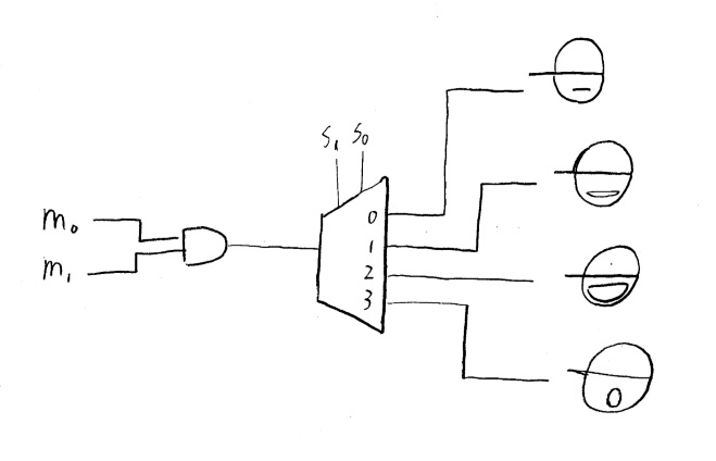
- Blue LEDs represent person with cap and Red LEDs represent lip.
- There are few things to consider:
- 1.We will set close lip (top left) as a initial state where amplitude and duration of signal is short.(A & K are zeros)
- 2.When high frequency of signal dominate low frequency, and if duration and amplitude is large, it will be wide open lip (bottom left). (A2 = 1, K2 >= K1)
- 3.When high frequency of signal dominate low frequency, and if duration and amplitude is small, it will be narrow open lip (top right). (A2 = 0, K2 >= K1)
- 4.When low frequency of signal dominate high frequency, it will be donut lip (bottom right). (K1 > K2)
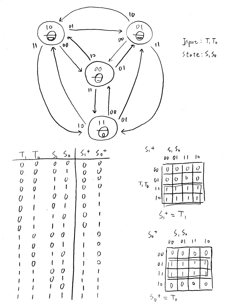
- K-map:
- Schematic:
- State diagram:
3.Parts
- Microphone
- BJT Transistors
- Voltage comparator
- Logic gates
- Resistors and variable resistors
- Switch for user input
- Capacitors
- Shift register
- Demultiplexer
- D flip flop
- 40~80 LEDs
4.Past and current Challenges
- Time constraint. Learning how to use new component take time and sometime we have to wait until parts to deliver.
- Filtering signal is a tricky subject where it would be cover more in the later course like ece210 and beyond.
5.References
Attachments:
Comments:
|
I love your guys' project! It might be challenging, but the topic and implementation line up very well with the what you've learned in lab, as well as what you will be learning in your next level of ECE courses. Your project is approved, but please feel free to ask for TA help along with the way, especially if you struggle with any of the signal processing. |
|
This is a really interesting idea for a project. I just have a couple of questions about your plans regarding certain aspects. Have you thought about how you are going to implement the square wave converter? Additionally, your plan to work from the bottom up, while admirable, may become difficult to realize in its entirety over the full scope of this project. You could consider using some sort of embedded DSP for dealing with some of the signal processing, if you so choose. |
|
This is possible DSP candidate: https://www.mouser.com/datasheet/2/268/70135G-35279.pdf |

