 |
CS440/ECE448 Spring 2020Assignment 2: Configuration Space PlanningDue date: Wednesday Febrary 19, 11:59pm |
Credits (Fall 2019): Zih-Siou Hung, Devansh Shah
Credits (Spring 2020): Heting Gao, Jialu Li
In this assignment you will write code that transforms a 2D planning problem for a robotic arm into a configuration space, and then searches for a path in that space. See Section 25.4 of the textbook and Lecture 7 for background information.
Contents
- General Guidelines
- Problem Statement
- Part0: Map Configuration
- Part1: Geometry
- Part2: Transformation to Maze
- Part3: Searching the Path in Maze
- Extra Credit
- Provided Code Skeleton
General guidelines
Basic instructions are the same as in MP 1. Your code must be in Python 3.6 or 3.7 and will be submitted to gradescope. Your code may import extra modules, but only ones that are part of the standard python library . Extra credit is capped at 10% (so the score for the MP will not exceed 110%).
Two changes from MP 1:
- In addition to the standard python libraries and pygame, you may import numpy.
- The extra credit portion will be submitted separately on gradescope.
For general instructions, see the main MP page and the syllabus.
You will need to re-use your bfs code from MP 1.
Problem Statement
For each planning problem, you will be given:
- The starting angles for the robotic arm.
- The locations (x,y) and radius r of circular goals.
- The locations (x,y) and radius r of various circular obstacles.
More details can be found in Map Configuration.
You need to find a shortest path for the robotic arm from its starting position to any of the goals so that the tip (open end of the arm) touches or is inside the goal and the number of steps rotating the arm is minimized.
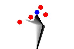
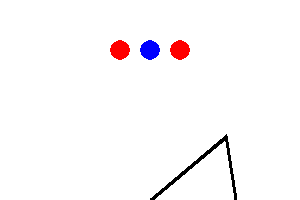
The tricky bit is that the robotic arm may not pass through any of the circular objects including a goal and an obstacle. Also, any part of the arm should not get out of the given window. So configurations like the following are NOT allowed:
You will do your path planning in two steps:
- Compute a configuration space map (Maze) that shows which joint angles are blocked by obstacles or by the window.
- Use your code from MP 1 (search.py) to compute a shortest path in this configuration space map. Use the bfs search algorithm for search.
For compatibility with MP 1, you will digitize the angles \(\alpha\) and \( \beta \) when creating your configuration space map so that the map will only be an approximation to real life. Also, the arm is allowed to only change one of \(\alpha\) or \( \beta \) in one step. Each step will change one of the angles by a fixed number called the angular resolution that is measured in degrees. The angular resolution will be an input parameter to your method, so that it can be adjusted for your tests and for our evaluation of your code. There is a tradeoff here: finer resolution will allow the arm to get through smaller gaps between obstacles but it will also slow down your search.
Part 0: Map configuration
First of all, you need to understand the 2D space that describes a robotic arm, a goal, and obstacles. The following example map, named 'Test1', would help you to understand map configuration specifications.[BasicMap] Window : (300, 200) # (width, height) ArmBase : (150, 200) # (x-coordinate, y-coordinate) ArmLinks : [ (100, 95, 5, (0, 180)), # (length, initial angle, padding distance, (min angle, max angle) (50, 60, 5, (-150, 150)), ] Obstacles : [ (125, 70, 10), # (x-coordinate, y-coordinate, radius) (80, 90, 10), (165, 30, 10), (185, 60, 10) ] Goals : [ (150, 50, 10), # (x-coordinate, y-coordinate, radius) (100, 50, 10) ]
-
- Window: The window size for the given example map is 300x200 pixel. Note that (0, 0) is the left-top corner and (300, 200) is the right-bottom corner.
- ArmBase: The arm base is placed at (150, 200).
- ArmLinks: There are two arm links.
-
- length: The length of the first arm link is 100.
- initial angle: its initial angle (\(\alpha\)) is 95.
- padding distance: The minimum distance between the arm link and the obstacle is 5.
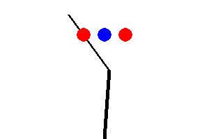
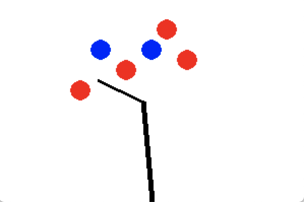
- The arm link should be at least 5 units away from the obstacles (goal and window boundary from the arm link do not apply this rule). This sample output helps you visualize the padding distance.
- You do not need to consider padding distance when computing if the arm links touch the window boundary or the goal.
- You will need to compute distance between a point and a line segment.
- (min angle, max angle): The minimum and maximum angle for this arm link is 0 and 180.
- The second arm link can be explained in the same manner.
- Obstacles: There are 4 obstacles with specified coordinates and radius
- There are two goals with specified coordinates and radius.
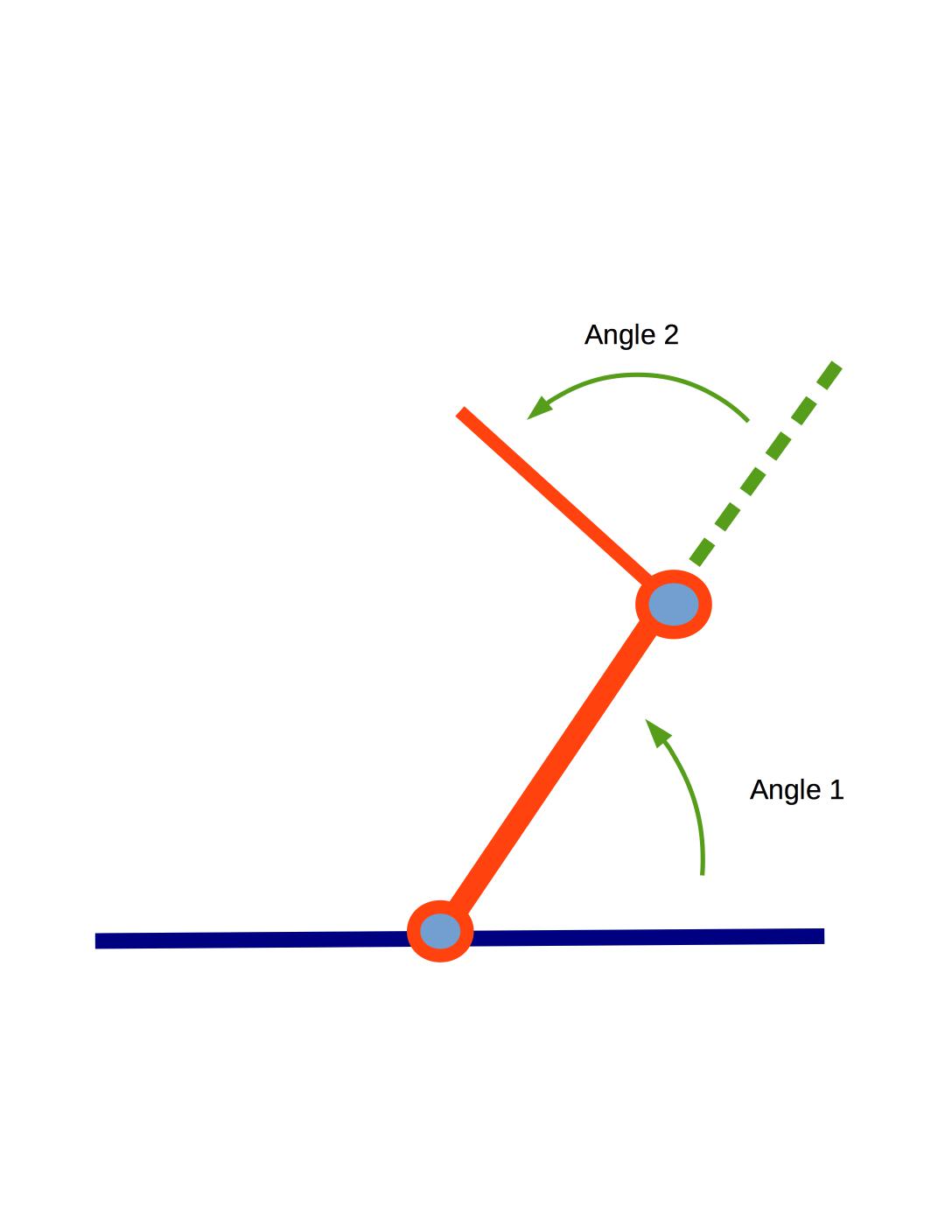
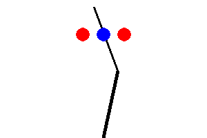
Look carefully at the conventions for \(\alpha\) and \(\beta \) in the diagram at the top of this page. Both angles are measured counter-clockwise. \(\alpha\) is relative to the ground and \(\beta \) is relative to the direction of link-1.
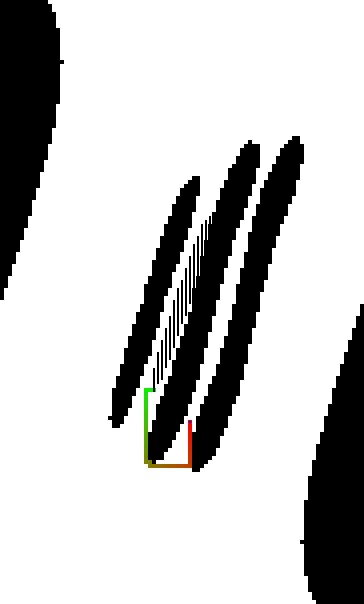
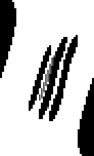
There are four obstacles, each of them is described in tuple (x-coordinate, y-coordinate, radius). Goals can be described in the same convention. Multiple goals are given; however, you only need to reach one goal with the fewest steps. The generated 2D map for above configuration is shown in the following:
You can play with the maps (stored in config file "test_config.txt") with the following command if your geometry functions are correctly implemented:
python3 mp2.py --human --map Test1 --config test_config.txt
Feel free to modify the config file to do more self test.Once the window pops up, you can rotate the arm using the following keys:
- z / x: increase / decrease \(\alpha\)
- a / s: increase / decrease \(\beta\)
- q / w: increase / decrease \(\gamma\) (if you have 3 arm links)
Part 1: Geometry
The first part of this MP is to work out the geometrical details.- getBase(): Return (x, y) of the arm base
- getArmAngle(): Return relative angles of all arm links. If there are two arm links, the return value would be (alpha, beta)
- getArmLimit(): Return (min angle, max angle) of all arm links
- setArmAngle(angles): Set angles(alpha, beta) for all arm links
- getEnd(): Returns (x, y) of the arm tip
- getArmPos(): Returns (start, end) of all arm links
- getArmPosDist(): Returns (start, end, distance) of all arm links
The next geometry problem is then to check whether
- the arm tip (the open end of the arm) touches or is inside the goal.
- the arm runs into obstacles distance less than the obstacle's padding distance. Note that the goal should be also considered as an obstacle with 0 padding distance unless the robotic arm tip touches it.
- all parts of the arm remain in the given window.
To do this, you need to implement the following functions:
- doesArmTipTouchGoals(armEnd, goals): Return True if the given arm tip position is anywhere in the given goals, including the boundary. Otherwise return False.
- doesArmTouchObjects(armPosDist, obstacles, isGoal): Return True if the given arm touches any obstacle or goal (depending on isGoal variable), including the boundary. Otherwise return False.
- isArmWithinWindow(armPos, window): Return True if all parts of the arm are within the window. Otherwise return False.
Once all geometry related functions are implemented, you can check whether the functions are correct by manually controling the robotic arm. You will get a 'SUCCESS' message when the arm tip touches anywhere of the goal. We also provided local test cases for you, and you can check it by simply running python3 geometry.py.
Part 2: Transformation to Maze
- Initial alpha and beta would be the starting point.
- The alpha and beta at which the arm tip touches the goals would be the goals in the maze.
- The alpha and beta at which the arm cannot reach (touching the obstacles, touching the goal but not using the arm tip, reaching outside of the window, etc) would be the walls in the maze.
- To contruct walls and goals, you need to use geometry functions defined in Part 1.
Your main effort for Part 2 would be to implement the following function.
- transformToMaze(arm, goals, obstacles, window, granularity): This function will return the maze instance created based on the given input arguments.
- The input arguments are:
- arm (Arm): arm instance
- goals (list): [(x, y, r)] of goals, where x and y are coordinates, and r is radius
- obstacles (list): [(x, y, r)] of obstacles, where x and y are coordinates, and r is radius
- window (tuple): (width, height) of the window
- granularity (int): unit of increasing/decreasing degree for angles
- Hint: use utils.py.


python3 mp2.py --map Test1 --config test_config.txt --save-maze [MAZEFILE_PATH]
python3 mp1.py [MAZEFILE_PATH]Note that maze.py in MP1 and MP2 is slightly different, so please do not use MP1 maze.py for MP2 and vice versa.
Part 3: Searching the path in Maze
Extra Credit
- self.get_map() in maze.py. The map returned should have 3 dimensions in the order of (alpha, beta, gamma)
- self.get_start() in maze.py. The start position returned should have 3 dimensions in order of (alpha, beta, gamma)
- search() in search.py
- transformToMaze() in transform.py
Provided Code Skeleton
The code you need to get started is in zip file. You will only have to modify following files:
- geometry.py
- transform.py
- search.py
- maze.py (modify and submit this only for the extra credit part)
Do not modify other provided code. It will make your code not runnable.
To understand how to run the MP, read the provided README.md or run python3 mp2.py -h into your terminal. The following command will display a 2D map and let you control the robotic arm manually (q and w for link-1, a and w for link-2, z and x for link-3).
python3 mp2.py --human --map [MAPNAME] --config [CONFIGFILENAME]
You can also save your output picture using --save-image option. If you want to export your maze to the text file, use --save-maze option.
The following command will run your bfs search method on the maze.
python3 mp1.py --method bfs --map [MAZEFILE_PATH]
Tips
- Think about how to accurately compute the distance between a line segment and a point.
- When constructing the maze, start with the bruteforce algorithm and then think about the shortcuts.
- When loading the maze in mp1.py, if the maze map size is too big, control the size using --scale option to make a proper size.
Deliverables
This MP will be submitted via gradescope.Please upload search.py, transform.py, and geometry.py at once to gradescope for MP2.
For extra credit, upload search.py, transform.py, geometry.py, and maze.py at once to MP2_extra.
Do not submit extra files to gradescope.
-