| Name | NetID | Section |
|---|---|---|
| Asaiah Rock | alanar2 | ECE 110 |
| Akash Chandra | akashc3 | ECE 110 |
Statement of Purpose
The purpose of our project is to create a modular analog device that converts electrical sound input sent through an audio jack based on touch input. The main interface of the device will be a touch screen overlay, which will be able to coordinate what changes to the output are desired, based on the specific point on the screen that is touched. In other words, the user will be able to control any effects parameters within the system with the touch of a finger. We will also build a few synthesizer modules which will be coordinated with the touch screen overlay to change the sound output.
Background Research
Please provide details on the background research your group has done for your project. Explain what drives you to work on this project and/or why this project is important. Also include discussions on any similar projects your group have looked at in coming up with your project. How is your proposed project different or similar to those your group have looked at.
The initial interest for this project originated from the Korg Kaoss Pad, a real-time effects processor/sampler, which has a total of 150+ effects that can be implemented. In the early 2000s, the Kaoss Pad was popularized by rock music artists, such as Muse guitarist Matt Bellamy, who was often seen playing a guitar with a built-in touch screen controller for a Korg Kaoss Pad. While the complexity of this device is much too high to be recreated for the purpose of this project, we are intrigued by the possibility of expanding the alteration of live instrument output from such a device. Additionally, the Kaoss Pad models are quite large; for more ease of mobility for musicians, without a need for wireless communication to a device such as the Kaoss Pad, a smaller, less extensive effects processor/sampler may be ideal. Devices such as the Kaoss pad require analog output from the instrument to be converted into digital input, which then must be converted into analog output to be sent to an amplifier. Since these conversions go beyond the scope of our project, we have decided to stick to simpler audio changes that would not require digital playback (thus excluding effects such as reverberation, looping, and echo).
One aspect that we have to consider is how sound will initially be electronically communicated. For string instruments that create sound vibrations, usually sound can be converted through a piezo, attached to an area with a large amplitude of vibration. Additionally, these instruments often have a pre-amp attached, which adjusts the output sent to an amplifier. Examples of this would be electric violins, violas, cellos, and acoustic-electric guitars. There are also electric wind instruments, which are actually more like synthesizers. These devices change output depending on the amount of air sent through the mouthpiece, as well as how the mouth piece has been shaped. For instruments in which metal components are vibrating, such as with electric guitars, pickups are placed close to the vibrating components to transfer the vibrations into electronic output.
-basic synthesizers (adjustable resistance, etc)
-variable input
-multiphonic expression and multiphonic expression controllers (use on touch-sensitive keys)
The distortion circuits will be made using Moritz Klein's youtube channel, as well as this forum as inspiration. We are planning on making a fuzz factor circuit, as well as an overdrive circuit to distort the guitar pickup output. The following schematics are being used as inspiration, with the first two images being closest to what we hope to emulate:
Block Diagram / Flow Chart
Provide a simple block diagram of your hardware design. A block diagram is a schematic graphic that shows the interactions between different components in a hardware or software system. If appropriate, please also include a flow chart showing the steps your design needs to go through to function. The online program draw.io is a great tool to create polished block diagrams and flow charts. Likewise Microsoft's visio is also a great program to create block diagrams and flow charts.
System Overview
Provide descriptions to your block diagram and flow chart. State the purpose of each block.
The audio in is to connect the initial signal from the guitar pickups to the distortion circuits. The audio out connects to a generic guitar amplifier to amplify the final signal to a fitting degree. The audio interprets signals sent from the touchpad to result in analog outputs that are connected to potentiometers within the guitar pedal circuits. These sent analog signals affect the voltage dividers, emulating the turning of the potentiometers connected.
Parts
Provide a list of parts that you may need for your project. You should include details such as the quantity, model number, purpose, vendor, and price (excluding taxes and shipping) for each part. This list may change as you work on your project.
| Item | Model Number | Vendor | Price (ea) | Quantity | Link |
|---|---|---|---|---|---|
| Product ID: 3575 | Adafruit | $2.50 | 1 | Link |
| 1676 | Adafruit | $14.95 | 1 | Link |
| PDB241-E420K-504A2-ND | Digi-Key | $2.85 | 3 | Link |
| 102-4790-ND | Digi-Key | $2.40 | 2 | Link |
| SC2384-ND | Digi-Key | $2.98 | 1 | Link |
| 987-1294-ND | Digi-Key | $0.70 | 3 | Link |
9V battery clip | 233 | ECE Supply Store | $0.48 | 1 | Link |
| 1321 | Adafruit | $1.50 | 1 | Link |
| 30157300 | ECE Supply Store | $1.50 | 6 | Link | |
| 60206250 | ECE Supply Store | $1.02 | 2 | Link | |
| 150301250 | ECE Supply Store | $18.23 | 1 | Link | |
| 150302500 | ECE Supply Store | $9.21 | 2 | Link | |
| 150367500 | ECE Supply Store | $12.80 | 1 | Link | |
PDB241-S420K-254A2 | Digi-key | $4.79 | 1 | Link | |
| Mouser | 0.96 | 3 | Link | ||
| Large Breadboard | Honors Lab Inventory | free | 1 |
Worth noting for later:
https://www.amplifiedparts.com/products/synth-eurorack-parts-diy?filters=2341a3253
https://www.instructables.com/The-5-Karduinoss-pad/
https://www.reddit.com/r/arduino/comments/cqupps/need_help_using_an_old_laptop_touchpad_as_an_xy/
Github repo: https://github.com/AkashChandra-02/XY-Touch-Pad-Effects-Controller
Possible Challenges
Please list some of the challenges that your group foresee in working on your project.
We first need to make sure that the guitar pedal effects work both individually, and when they are connected together in series. This means that there can be no errors in these circuits. Additionally, it will be difficult to test these circuits on a breadboard, as components could come loose while playing the guitar connected. We will also have to play around with the variance in analog output signals from the Arduino.
References
List all references you used in your proposal. This is important, you do not want to be blamed for plagiarism. IEEE citation format is highly recommended. You can use citethisforme.com's IEEE citation generator to painlessly generate your references in this style.
https://www.instructables.com/Kass-Pad-Guitar-Midi-Controller-Microcontroller-/
https://amptonelab.com/products/xy-midipad/
https://en.wikipedia.org/wiki/Electric_cello
https://en.wikipedia.org/wiki/EWI_(musical_instrument)
https://forum.pedalpcb.com/threads/lfos-part-i.4648/
https://www.parasitstudio.se/building-blog/category/all/3
https://web.archive.org/web/20011212123517/http://users.chariot.net.au/~gmarts/ampovdrv.htm
http://www.geofex.com/article_folders/fuzzface/fffram.htm
Demo pictures (Full size pictures are at the bottom):
Please check the github for updated code.
This is the first working pedal, the Fuzz pedal. This reading is a little flawed since I misplaced the ground connection.
These are the pedals combined, before we added the Arduino.
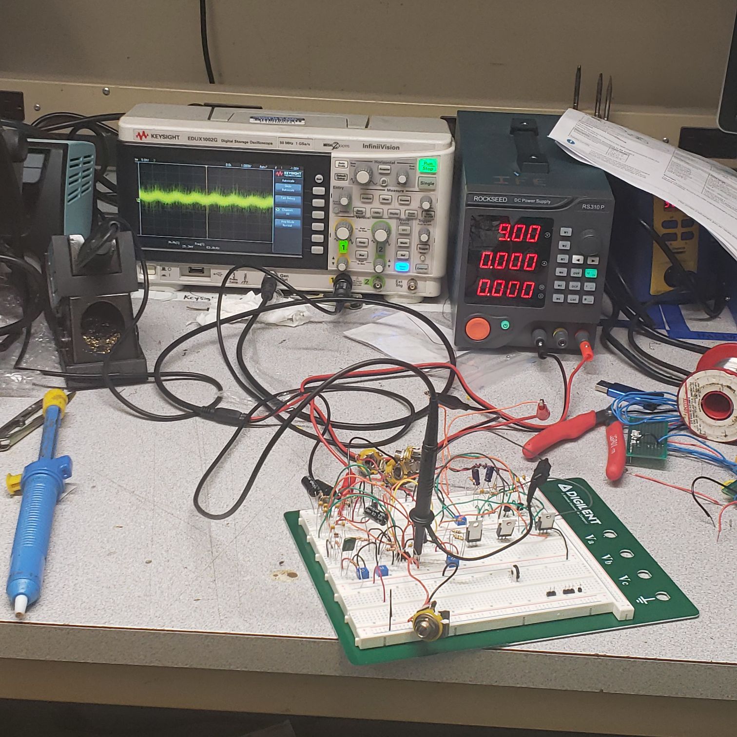
Setup for the next to pictures. We used a 500mV 700Hz sine wave.
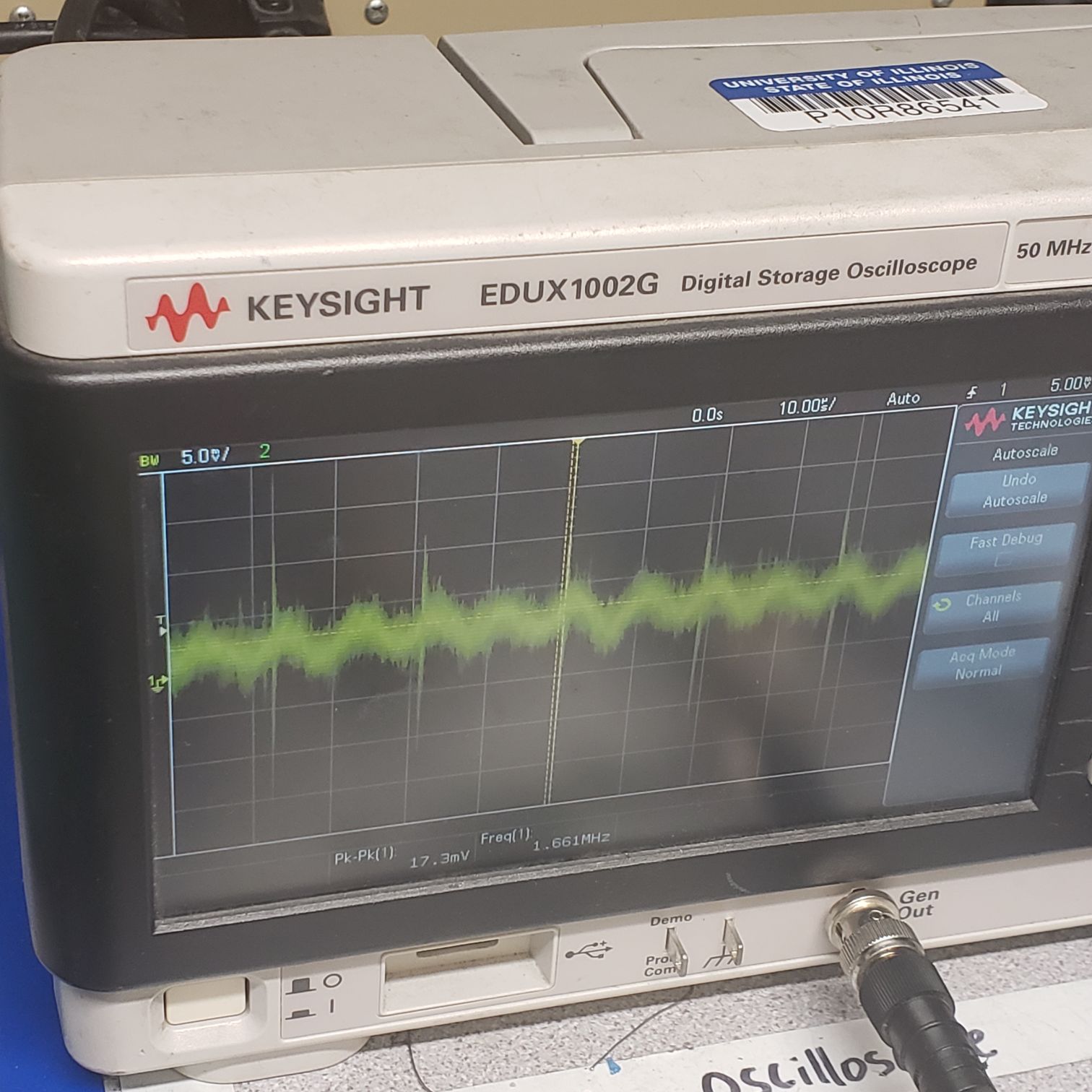
This is the first working singal of both effects combined. Here, the volume was not at full. We see that we have 17 mV peak to peak.
Here, the volume is at max, so we have 19 mV peak to peak.
This is the final output, with the arduino modulation. The reason for the "steps" is because the MOSFETs are being fed a PWM signal, so that is why we see the "steps".
Full size pictures begin now:


