Group Members: Lucy X. and Smit P.
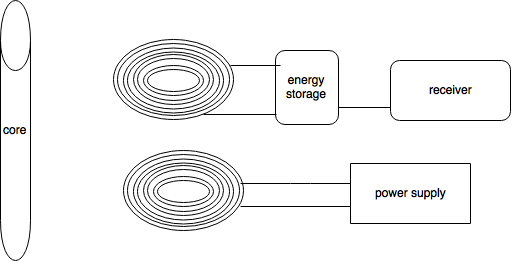
We plan on making a wireless charger that works across various devices.
week 1
we discussed our idea and made plans for that. We intended to make a wireless charger or the phone made of plastic first because it is more simple than the one made of metal which will generate heat during charging.
week 2
we explored the principles of the wireless charging technology. The induced current in the loop is cause by the change in flux, which is the number of magnetic lines that go into the area of the loop. According to the Lenz Law, https://en.wikipedia.org/wiki/Lenz%27s_law, an opposite EMF will be induced to try to decrease the change in flux in the loop
week 3
we began our test of lighting an LED
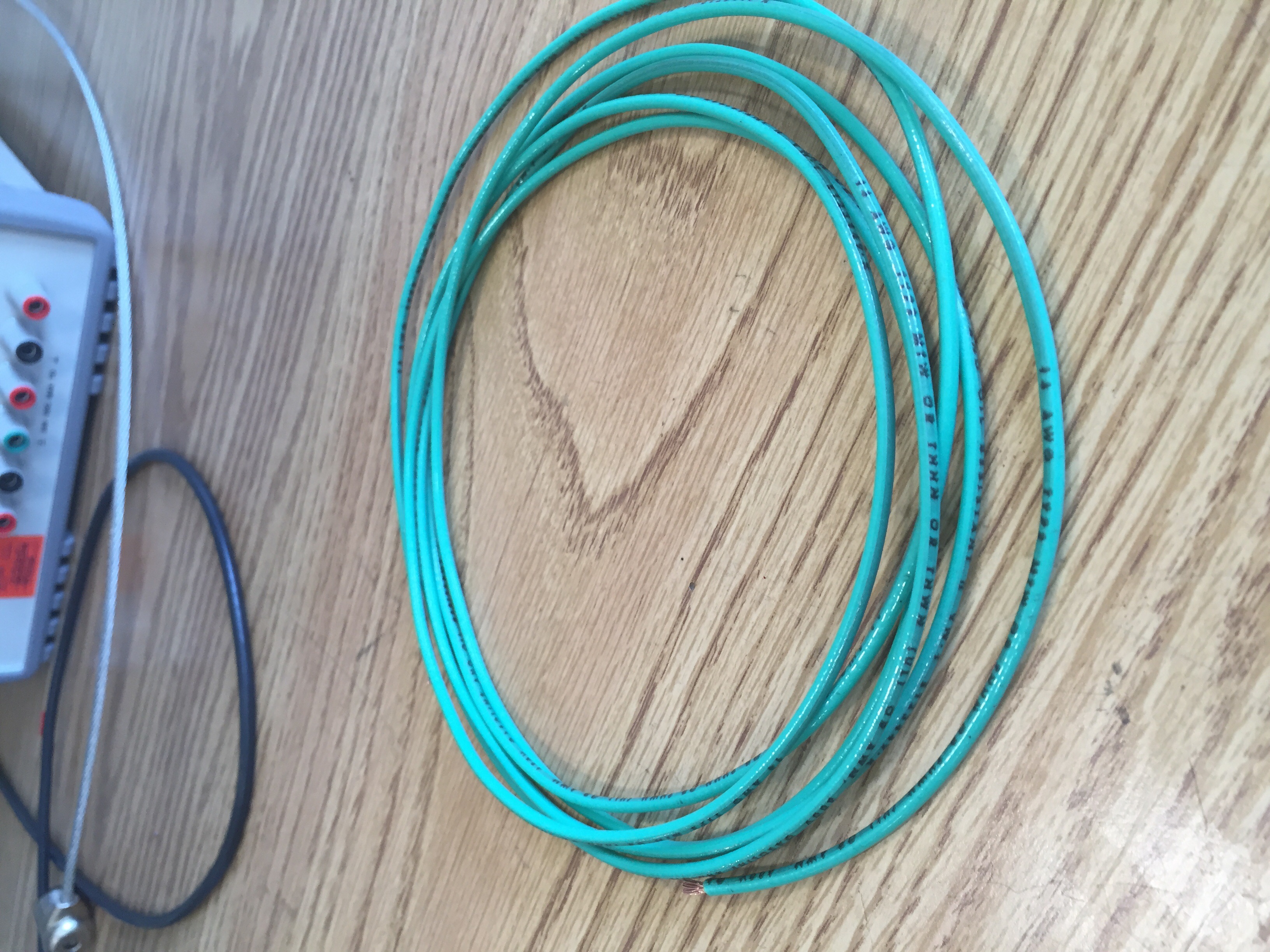
we got some coils and LEDs to set up our circuit
week4
we tried to light the LED but failed, trying to figure out why our assumption is not working
week 5
We thought that it was perhaps the current is to low in the circuit as a result the produced magnetic field is too weak
We tried to increaser the current and burned a resistor
week 6
Instead of trying to light the LED using the DC by moving the LED above the circuit, we tried to use the AC
In this way, the speed of the change of the flux should be higher, thus the current induced should be big enough to light the LED, according to EMF=-d(flux)/dt
week 7
We explored and discussed further on the principles an formulas involved and did some calculation on how much AC current we may need to light the LED
Then we went to the ECE110 lab downstairs seeking the AC power supply but we did not find one
week 8
Since this plan is hard to implement with what we have now, we decided to change our plan
After exploring, understanding, thinking over the instructions on a website, we found the guidance made sense and feasible, therefore, we began to produce something new with the guidance
week9
We discussed what we need to carry out our plan
We checked these parts in the shop downstairs and made an order list for the rest we did not get in the shop
week 10
Most of the parts for our circuit are here, we built the circuit and tried to test itimage.jpg

