Rajat Thaker - rthaker2
Aaron Gros - aygros2
Introduction
Statement of Purpose
Outfitting LEDs onto a longboard is one of the most common aesthetic modifications one can make to a board, but this feature usually calls for a hand-held control involving an overcomplicated system of LED RGB outputs that are manually changed. Our goal is to not only outfit our board with LEDs but to also make them modulate in different patterns based on the level of vibration the board is feeling. Using an accelerometer, peizo sensor and Neopixel LED strips, our aim is to outfit our board with an aesthetic design that changes color based on the vibration sensed by the accelerometer and piezo sensor.
Background Research
- Neopixel LEDs are strips of LED lights created by Adafruit. They are programmable by a microcontroller and can be coded by either individual "pixel" or as one full unit we call the full, immediate change of a color strip a "show" of colors because the command to change them is lightArray.show(). As shown in this code example, pixels use RGB ranging from 0 - 255 (each) which allows for each pixel to be programmed using 4 parameters: n (the index of the pixel starting at 0), R (the red value), G (the green value), and Blue (the blue value). The pixels also have another useful programmable option which is that they can be programmed using only two parameters, one of which is n and the other being a single numerical value that represents color.
- A piezoelectric sensor will detect the vibration of the board. This component outputs a small voltage when deformed by a certain amount. When this happens the piezo outputs a voltage between 0 and 5 V that can then be converted through an Analog to digital converter (ADC) that will output a value from 0 - 1023 that can then be read by the Neopixel strips
- The accelerometer contains three accelerometer(one for each axis). It has three output wires, one for every axis, which will output a voltage in between 0 and 5V depending on the accelerations each axis feels. These values can be converted with an ADC to a value from 0 to 1023.
Design Details
Flow Chart
System Overview
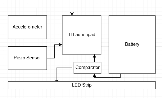
The power supply unit will be powering the launchpad, accelerometer, piezo sensor, the LED strip and the comparator. Since the battery will output 12V we will need to regulate it to give each component the appropriate voltage.
- The piezo sensor and accelerometer will output voltage values to the launchpad based on how much vibration/acceleration they feel.
- The launchpad will read the output of the piezo sensor and accelerometer and based on those values it will determine the patter and colors for the LED strip. Once it determines these values it will output them to control the LED strip
- The comparator will compare the voltage level of the battery to a value to determine if it's under a certain voltage level and cut off the power if it is.
Parts DONE
- 1 TI Launchpad
- 1 Accelerometer https://www.amazon.com/MPU-6050-MPU6050-Accelerometer-Gyroscope-Converter/dp/B008BOPN40/ref=sr_1_3?ie=UTF8&qid=1539128372&sr=8-3&keywords=accelerometer
- 1 Piezo Sensor https://www.amazon.com/DIKAVS-Enclosed-Piezo-Element-Alarm/dp/B073FCGCYB/ref=sr_1_18?ie=UTF8&qid=1539128487&sr=8-18&keywords=piezo+sensor
- Buck Booster: https://www.sparkfun.com/products/9370
- MOKUNGIT (<$50) https://www.amazon.com/Mokungit-WS2812B-Programmable-Addressable-Non-Waterproof/dp/B019HAAVLQ/ref=sr_1_4?s=lamps-light&rps=1&ie=UTF8&qid=1539301973&sr=1-4&keywords=individual%2Baddressable%2Bled%2Bstrip&refinements=p_85%3A2470955011%2Cp_36%3A1253528011&th=1
- Batteries (<$50) https://www.amazon.com/Panasonic-NCR18650B-3400mAh-Protected-Batteries/dp/B00NUI47OY
- battery case https://www.amazon.com/Battery-Holder-2x18650-Rechargeable-Batteries/dp/B00H8UWGIO
- Potentiometer https://www.sparkfun.com/products/9806
- Comparator https://www.sparkfun.com/products/13950
- Connecting parts (wires/soldier/breadboard, etc.)
Possible Challenges
Programming the accelerometer to give readable output for vibrations.
Compressing the system to give readable output for vibrations.
Power diversion.
designing the circuit for the comparator
- FINAL PROJECT LAB REPORT
Code:
#include<Wire.h>
#include <FastLED.h>
const int MPU_addr=0x68; // I2C address of the MPU-6050
#define LED_PIN 5
#define NUM_LEDS 60
CRGB leds[NUM_LEDS];
int16_t AcX,AcY,AcZ,Tmp,GyX,GyY,GyZ,piezoVal;
int pulse = 30;
int count = 0;
void setup(){
setupWire();
FastLED.addLeds<WS2812, LED_PIN, GRB>(leds, NUM_LEDS);
Serial.begin(9600);
}
void loop(){
updateWire();
//The Faster(larger AcY) you go the more LEDS turn on
int y = map(AcY, -4000, 4000, 0, NUM_LEDS/2);
for(int i = 0; i < NUM_LEDS/2; i++) {
int k = i + 30;
if(i <= y) {
//Blue if going straight, Green on inside of turn, Red on outside of turn
if(AcX >= 750) {
leds[i] = CRGB ( 255, 0, 0);
leds[k] = CRGB ( 0, 255, 0);
}
else if(AcX <= -750) {
leds[i] = CRGB ( 0, 255, 0);
leds[k] = CRGB ( 255, 0, 0);
}
else {
leds[i] = CRGB ( 0, 0, 255);
leds[k] = CRGB ( 0, 0, 255);
}
}
if(i == pulse && count < 3) {
leds[i] = CRGB ( 255, 0, 255);
leds[k] = CRGB ( 255, 0, 255);
pulse++;
count++;
}
if(i > y) {
leds[i] = CRGB ( 0, 0, 0);
leds[k] = CRGB ( 0, 0, 0);
}
}
count = 0;
if(pulse < 30) {
pulse--;
}
FastLED.show();
delay(50);
}
void setupWire() {
Wire.begin();
Wire.beginTransmission(MPU_addr);
Wire.write(0x6B); // PWR_MGMT_1 register
Wire.write(0x00); // set to zero (wakes up the MPU-6050)
Wire.endTransmission(true);
Wire.beginTransmission(MPU_addr); //Start communication with the address found during search.
Wire.write(0x1B); //We want to write to the GYRO_CONFIG register (1B hex)
Wire.write(0x08); //Set the register bits as 00001000 (500dps full scale)
Wire.endTransmission(); //End the transmission with the gyro
Wire.beginTransmission(MPU_addr); //Start communication with the address found during search.
Wire.write(0x1C); //We want to write to the ACCEL_CONFIG register (1A hex)
Wire.write(0x10); //Set the register bits as 00010000 (+/- 8g full scale range)
Wire.endTransmission();
}
void updateWire() {
Wire.beginTransmission(MPU_addr);
Wire.write(0x3B); // starting with register 0x3B (ACCEL_XOUT_H)
Wire.endTransmission(false);
Wire.requestFrom(MPU_addr,14,true); // request a total of 14 registers
AcX=Wire.read()<<8|Wire.read(); // 0x3B (ACCEL_XOUT_H) & 0x3C (ACCEL_XOUT_L)
AcY=Wire.read()<<8|Wire.read(); // 0x3D (ACCEL_YOUT_H) & 0x3E (ACCEL_YOUT_L)
AcZ=Wire.read()<<8|Wire.read(); // 0x3F (ACCEL_ZOUT_H) & 0x40 (ACCEL_ZOUT_L)
Tmp=Wire.read()<<8|Wire.read(); // 0x41 (TEMP_OUT_H) & 0x42 (TEMP_OUT_L)
GyX=Wire.read()<<8|Wire.read(); // 0x43 (GYRO_XOUT_H) & 0x44 (GYRO_XOUT_L)
GyY=Wire.read()<<8|Wire.read(); // 0x45 (GYRO_YOUT_H) & 0x46 (GYRO_YOUT_L)
GyZ=Wire.read()<<8|Wire.read(); // 0x47 (GYRO_ZOUT_H) & 0x48 (GYRO_ZOUT_L)
piezoVal = analogRead(A2);
Serial.print("AcX = "); Serial.print(AcX);
Serial.print(" | AcY = "); Serial.print(AcY);
Serial.print(" | AcZ = "); Serial.print(AcZ);
Serial.print(" | GyX = "); Serial.print(GyX);
Serial.print(" | Piezo = "); Serial.println(piezoVal);
if(piezoVal > 3) {
pulse = 0;
}
}
