Final project video:
Final project paper: https://docs.google.com/document/d/1dd16Rp-zndpMhm4J63uSv3dOQe0mQhZMYocxQb9i7LA/edit?usp=sharing
| Name | NetID | Section |
|---|---|---|
| Hyrum Dickinson | hyrumsd2 | ECE 120 |
| Oliver Johnson | owj2 | ECE 120 |
Statement of Purpose
Our project is to make an unbeatable Tic-Tac-Toe machine. We will build an Arduino-powered smart board that uses LEDs to display information to the user, and buttons that allow the user to interact with it. Because of the nature of Tic-Tac-Toe, a inerrant player will always win or tie a game, regardless of who goes first. We are confident that we can make our interactive Tic-Tac-Toe smart board to be that inerrant player.
Background Research
Students at Oakland University built a similar project using logic gates in 2018; however, their report documented an issue allowing players to overwrite existing moves, even though that violates the rules of Tic-Tac-Toe. Our project will overcome that disability by running all decisions through an Arduino rule-checker. In order to allow appropriate overwriting of moves, we will add a reset button to the configuration. In our project, buttons once pressed will remain locked in whatever state they are put in until the reset button is pressed.
Our team has studied the math behind Tic-Tac-Toe and found that an inerrant player will never lose. Using logic gates, we are confident that we can program our system to be the perfect player.
Block Diagram / Flow Chart
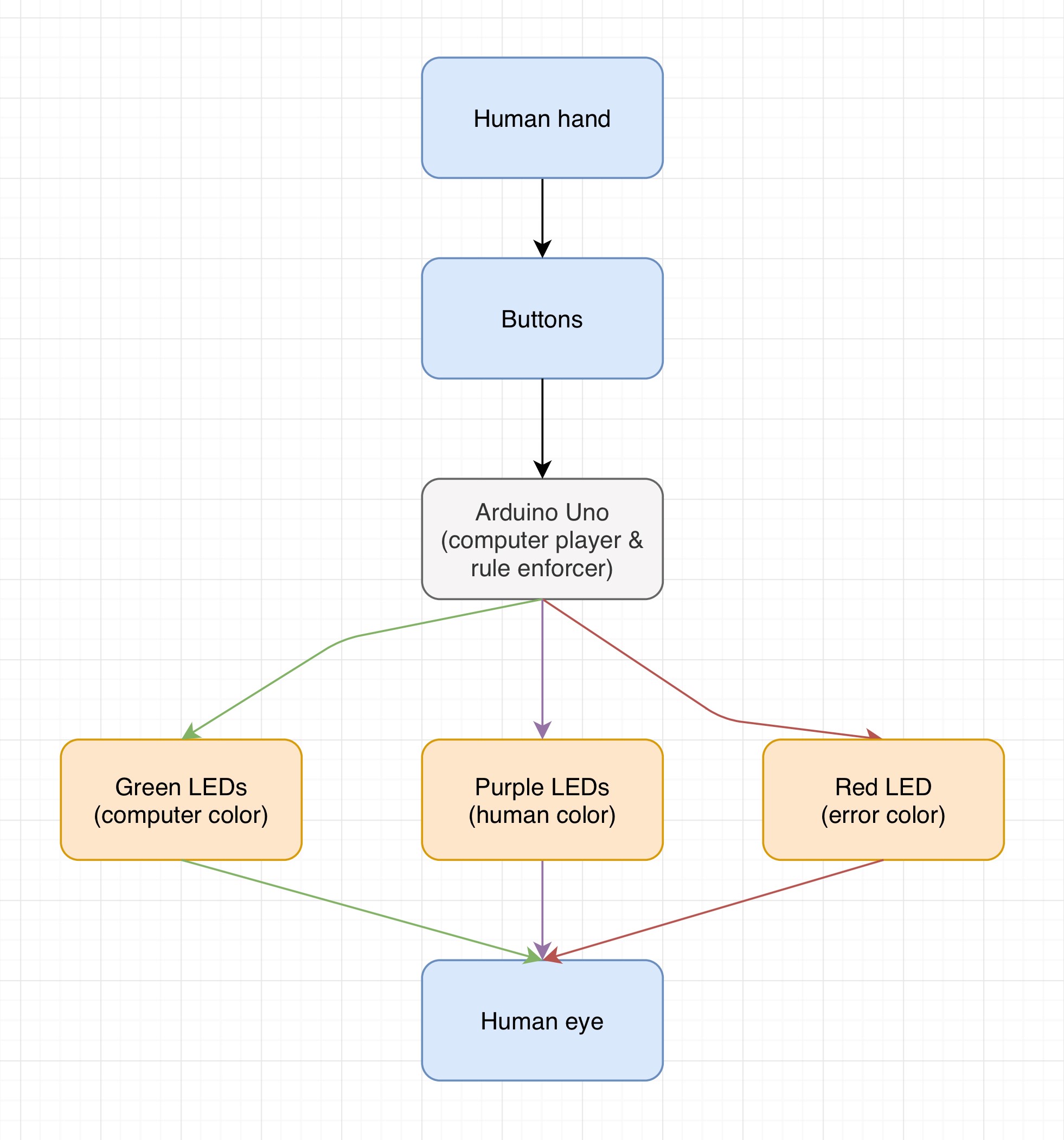
Input/output diagram: (this diagram has some issues and needs to be rewritten - switch human and computer colors, add code block that inputs to Arduino Uno)
Sequence diagram: (an arrow should be added from the blue loop box to the reset button box to reflect that the user may press the reset button at any time)
System Overview
The input/output diagram demonstrates the inputs and outputs of each major project component. Both ends of the input/output diagram are human-facing: users make the inputs that trigger all other decisions, and the ultimate end goal of the device is for outputs to be viewed by a user. In between the user inputting information and the device outputting information to the user, several layers intervene. First, there are the buttons. With the exception of users connecting and disconnecting the device and power, all user input enters the system via buttons.
All buttons wire directly to the Arduino Uno - the brain of the system. The microprocessor runs our custom Arduino code to determine what to do with each button's input. There are four things that the Arduino might do with a button's input:
- If the user clicked one of the nine "move" buttons: accept the move, light up the corresponding green LED, set aside the corresponding square in memory as a square where no further moves can be played, evaluate the position for a win or tied game with all squares filled, evaluate the position for the best computer player move, light up the corresponding blue LED to the computer's chosen move, set aside the corresponding square in memory as a square where no further moves can be played, evaluate the position for a win or tied game with all squares filled, and then await user input.
- If the user clicked on of the nine "move" buttons: reject the move, make the red LED blink several times, and then await user input.
- If the user click the "reset" button: wipe all data from the previous game, make all LEDs blink twice, turn all LED's off, and then await user input.
If at any time the Arduino evaluates the position to be a winning position, it will shut off all LEDs of the losing color, cause all LEDs of the winning color to blink several times, light up the LEDs such that they display the winning position, set aside all squares in memory as squares where no further moves can be played, and then display the game's final position while awaiting user input.
If the Arduino evaluates the position to be a tied game, it will cause all currently lit up LEDs to blink several times, and then light them up such that they display the tied game position, and then display the game's final position while awaiting user input.
The sequence diagram is a more self-explanatory diagram detailing the specific sequence in which actions should occur for the system to perform properly. The only major threat to proper sequencing is abuse of the system by the user - for example, pressing buttons so rapidly that multiple inputs hit the Arduino before the first has a chance to be completely processed. It is possible that the Arduino will process actions so fast as to make user input overload impossible. However, as a precaution, the Arduino will be coded such that it will not accept inputs until the previous input has been completely processed and all LED animations (like blinking light sequences) have completed.
At any time (when a previous input is not being processed) the user can hit the reset button, wiping the game and setting up a new round. The user may also at any time disconnect the system from power, effectually wiping all data from the specific ongoing game. The system should be designed such that a sudden disconnection from power at any point during operation of the Tic-Tac-Toe smart board will not damage the system, and such that a reconnection to power will always cause the system to simply begin again at the top of the sequence diagram.
Parts
- 1 Arduino Mega 2560
- brains of the system; chosen because we need its large quantity of digital input/output pins
- Honors Lab Inventory
- https://docs.google.com/spreadsheets/d/15G13wYiROCPM4tA4JizXmBHmO_kkZ96v7YTibe_z5Qg/edit#gid=0
- $39.95
- ordered using team funds
- 1 custom PCB / Arduino shield
- shell of the system
- vendor TBD
- link to specs TBD
- cost TBD
- will be ordered using team funds
- 10 Cathode RGB LEDs (red-negative-green-blue)
- outputs information from the system to the user
- 9 squares + 1 game status display
- https://www.amazon.com/gp/product/B077X95LRZ/ref=ppx_yo_dt_b_asin_title_o00_s00?ie=UTF8&psc=1
- $8.99 (for a pack of 100)
- ordered using personal funds
- 10 pushbutton switches
- inputs information from the user to the system
- 9 squares + 1 game status controller
- https://www.amazon.com/gp/product/B06XRH6GNX/ref=ppx_yo_dt_b_asin_title_o00_s00?ie=UTF8&psc=1
- $7.48 (for a pack of 50)
- ordered using personal funds
- Assorted resistors
- controls current to each LED color & to the Arduino
- exact resistances will depend on preferred LED brightness level after experimentation
- https://www.amazon.com/gp/product/B07GZR7K2C/ref=ppx_yo_dt_b_asin_title_o00_s00?ie=UTF8&psc=1
- $14.49 (for a pack of 2425)
- ordered using personal funds
- Assorted male header connectors
- connects the Arduino to the PCB shield
- exact amount used will depend on number necessary for Arduino Mega 2560
- https://www.amazon.com/gp/product/B06XR8CV8P/ref=ppx_yo_dt_b_asin_title_o00_s00?ie=UTF8&psc=1
- $6.97 (for a pack of 50)
- ordered using personal funds
Design Specifications
Schematic Parts
There are 9 squares on the Tic-Tac-Toe board.
For each square i, there are 6 components, with labels–specs–purposes as follows:
- LEDi - LED RGB Common Cathode 4-Pin (blue-green-ground-red) f5 5MM Diode - system output to user
- SWi - Momentary Tactile Touch Switch Push Button DIP P4 Normally Open - user input to system
- RiSW - 1/4 Metal Film Resistor - controls current through switch
- RiRED - 1/4 Metal Film Resistor - controls current through red
- RiGRN - 1/4 Metal Film Resistor - controls current through green
- RiBLU - 1/4 Metal Film Resistor - controls current through blue
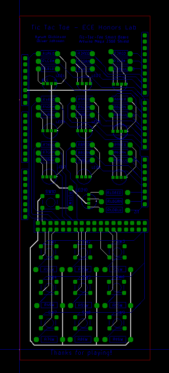
PCB Schematic
Wiki doesn't allow the uploading of Gerber files, as best I can tell. Here is a screenshot of the schematic as displayed in the KiCAD Gerber viewer.
Possible Challenges
- Writing the Arduino Uno code could be tricky. However, Hyrum does have experience writing game code and writing code for Arduino.
- Designing the custom PCB could be hard because neither member of the team has experience with Autodesk EAGLE.
- Debugging the electronics once physical construction commences may involve setbacks for the team; however, both Oliver and Hyrum have been involved in electronics construction before and have gained experience debugging difficult circuits.
References
Klements, M., 2021. Make An Arduino Tic Tac Toe Game With An AI Opponent. [online] The DIY Life. Available at: <https://www.the-diy-life.com/make-an-arduino-tic-tac-toe-game-with-an-ai-opponent/> [Accessed 7 October 2021].
Haq, R., 2021. Making a Tic Tac Toe game using Digital Logic Design. [online] Youtube.com. Available at: <https://www.youtube.com/watch?v=BTh91RYXhqQ> [Accessed 10 September 2021].
Kirschke, S., Loper, D., Strunk, D. and Galczyk, A., 2018. Tic Tac Toe Game. [online] secs.oakland.edu. Available at: <https://www.secs.oakland.edu/~llamocca/Courses/ECE2700/W18/FinalProject/Group10_TictactoeLEDs.pdf> [Accessed 10 September 2021].
List all references you used in your proposal. This is important, you do not want to be blamed for plagiarism. IEEE citation format is highly recommended. You can use citethisforme.com's IEEE citation generator to painlessly generate your references in this style.


