Shree Samavedhi, shree2, ECE 120
- Introduction
- Statement of Purpose
This project hopes to create a Theremin so that the user can control volume and pitch through carefully hovering their hands over the distinct antennas. - Background Research
My passion for music has always been prominent in my creative work; being a musician myself I decided it would be fascinating to discover the properties of electronic music by creating a Theremin from its basic components. Through first discovering this instrument through a variety of performances online, constructing the device would not only be of creative interests in order to explore a new realm of music production, but also an excellent opportunity to delve into the inner workings of electronic components, specifically in signal processing.
In order to design the circuit, I viewed many other attempts in which people created their own version of the Theremin. While there were plenty of circuits that only controlled pitch, I was more interested in combing pitch and volume together, in order to have a larger range of sound production. I was able to view a circuit diagram [1] that not only included both elements of volume/pitch in audio output but also containing an LED pannel for visually displaying the output. While I am not planning to have this LED output, I did find it an interesting concept to consider if I decide to add another output in the future. Currently, I have decided to construct a Theremin with volume and pitch antennas, leading to a singular audio output, allowing the user to compose music in real-time.
- Statement of Purpose
- Design Details
- Block Diagram/Flow Chart
- System Overview
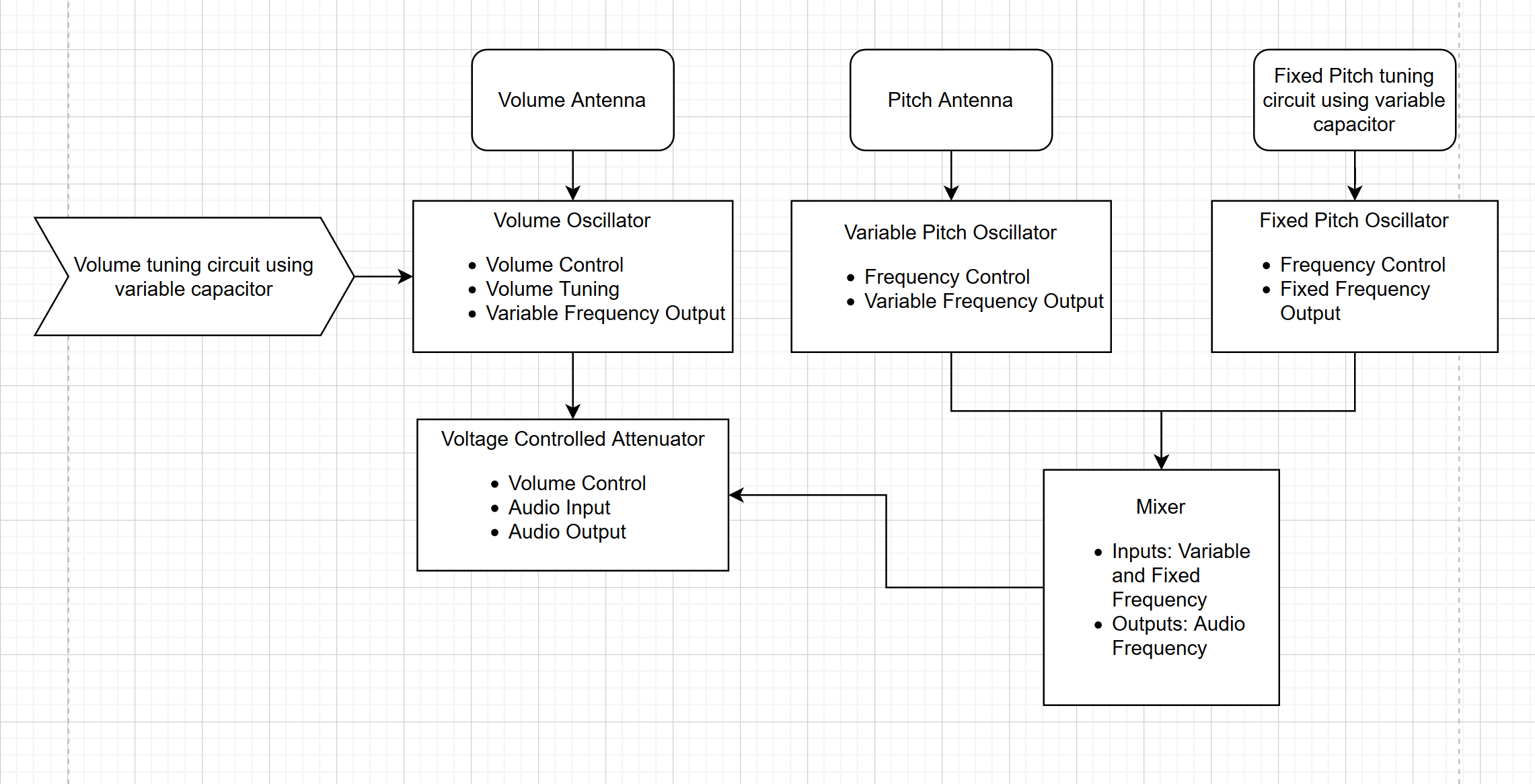
In this flow chart above, we notice there are two distinct inputs that finally lead to the singular audio output. Both the Volume and Pitch Antennas directly receive signals through capacitance change. Normally, this is done by connecting the antennas to LC resonant tank oscillators (when capacitance changes, frequency changes). You'll notice in the diagram, both Antenna's also output to Variable Oscillators, and that there exists a Fixed Oscillator component as well. The idea is that as a hand moves closer to the antennas, the frequency of the variable oscillators change, while the fixed oscillator remains constant, producing a single frequency difference which can then be used directly as an audio signal. The final piece before outputting to Audio is the Voltage Controlled Attenuator, which provides a volume range from the mixer (which would otherwise output at full volume). Finally, all these components output through a speaker to accurately represent the volume and pitch changes made by the user.
- Block Diagram/Flow Chart
- Parts
Due to the amount of circuitry involved in this project, it will require a lot of specific circuit elements. While it would be impossible to list each and every-one, notable elements include the two antennas, Battery Powered Speaker, and a 12 Volt power supply. The other individual components that will be used to breadboard will be resistors, capacitors, plenty of Op-Amps, and the physical breadboards themselves. When putting the Theremin together, it also would be helpful to have a wooden block to place both antennas, and a clasp of some sort to hold them in place.
Parts List Edit:
8/3" aluminum tube straight Pitch Antenna
8/3" aluminum tube circular Volume Antenna
Wood Board
4 Copper Clasps
https://drive.google.com/open?id=136tUAQ7guTF9s902ys1ZNNW5ck3SE2xZ - Possible Challenges
Due to this project having two inputs, two from the Volume and Pitch Antenna, as well as having to go through several signal changes before emitting to the output, I would imagine there would be several debugging issues since every component must work as planned. Due to this, I intend on building an testing every component first individually, before combing them together, as a means to minimize potential error. I'm especially cautious for the Fixed and Variable Oscillators to provide enough of a frequency difference in order to measure and output since that requires two components being dependent on each other. - References
[1] Brito, P., Gomez, D. and McCabe, P. (2016). 6.101 Final Project Theremin. [online] Available at: https://web.mit.edu/6.101/www/s2016/projects/ [Accessed 17 Feb. 2020].
