Akeem Kennedy ajkenne2 ECE110/Zefeng Zhang zefengz2 ECE110/Abhishek Bhandari/anb4
1.Introduction
a. Statement of purpose
Our project is to build a remote that could control the window shades and the light switch in our rooms. We have high-loft beds and it is a bit of a problem to manually switch the light off before we go to sleep. In the morning, the penetrating sunlight can be so discomforting and climbing out the bed and changing the window shades is inconvenient. The remote control can pull down the shades when required and change its orientation such that it is at an oblique angle to the sunlight.
b. Background Research
The major source of our motivation to have a project like this comes primarily from our reluctance to do all the manual work. A similar project might be the Remote Light Switch by Maddie Wilson, Mingle Xiao, and Pranav Perepa in Spring 2016. Our project is different because we want to design a device that can control the movement and orientation of the blinds rather than just the light switch. The tech giant Google has invested heavily in Google Home which is a voice activated product that enables one to utilize one's entire house's functional capabilities from anywhere. Other products on the market such as Simple Control works with a Z-Wave controller. The Z-Wave controller is an app that allows the user to set timers and control their blinds, with only one click, the light can be dimmed without bothering you to switch it off manually. But also the Smart Blinds is an automated Solar-power blinds that are controlled with your phone or a smart switch. All-in-one device with eco-friendly design. Our design is different from theirs because ours use infrared red.
2.Design Details
- Block Diagram / Flow Chart
- System Overview
The device will work in the following manner:
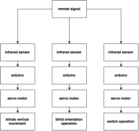
1) When one of the buttons on the remote is pressed, an infrared beam will be emitted which will be detected by the infrared sensor. This will cause the metal rod attached to the servo motor to either turn clockwise or anticlockwise depending on whether the "switch on"/"switch off" button is pressed. In its resting position, the rod would be parallel to the ground and the 2 other positions that it will be able to move to would be at around 140 degrees from its resting position in the clockwise and anticlockwise direction. The idea is that if the lights are off (say), and you press the "switch on" button, the rod will swing in the anticlockwise direction and push the switch into the "on" position. After this it will move back to its resting position( so that the switch can also be turned off manually if so desired).
2) When the button that changes the orientation of the blinds is pressed, an infrared signal will be sent to the infrared sensor. This will direct the servo motor to turn either clockwise or anticlockwise by a certain number of a degrees to a certain orientation. There will be a certain number of fixed positions(in terms of angles rotated) to which the servo motor can rotate. This can be controlled by the number of times the button is pressed. This servo motor in turn will be connected to a plastic rod(already part of the curtain!) that when rotated changes the orientation of the blinds. Normally we have to turn the blinds manually, but by using the remote controlled servo motor we can turn it using the remote.
3)When the button that controls the blinds movement is pressed, and infrared beam signal will be sent. The infrared sensor will detect the signal and the servo motor will rotate. The servo motor will be interlocked with the chain of the curtain such that the tension is maximum in the chain and each protruding part of the motor wheel interlocks with the beads of the chain. In this manner the motor's rotation will cause the curtains rotation. To keep the blinds turning the button needs to be kept pressed.
- Block Diagram / Flow Chart
LOW- LEVEL DESIGN
3.Parts
- Infrared Red Sensor
- Arduino
- Breadboard
- Laser
- Servo Motors
4.Possible Challenges
- All three of us are taking ECE110 so programming the Arduino may be challenging.
- Getting the individual sheets of shade to rotate simultaneously
5.References
- Infrared-Light Sensor Set Up
- Update 20: SmartSwitch is coming! · Automate your blinds with a smart control kit in. (n.d.). Retrieved September 23, 2016, from https://www.kickstarter.com/projects/551966671/automate-your-blinds-with-a-smart-control-kit-in-1/posts/1606025
- Z-Wave Home control | Z-Wave Home control. (n.d.). Retrieved September 23, 2016, from http://www.z-wave.com/
XXX XXXXX Retrieved XXXX From XXXXX
6.Weekly updates
- Sep 30th-Oct 7th: We've ordered the infrared sensors and servo motors needed for this project and worked out the low-level design.
- Oct 9th -14 : We ordered more parts and we began assembling the components of the infrared detector. We had to dismantle it once we were done because the parts didn't belong to us; we had borrowed them from our TA.
- Oct 14th -21st: we decided to focus on the infrared sensor remote controlled switch first because our servo motors might take another 2 weeks to arrive. We have made some progress on the code needed to run the servo motor, and we discussed the circuitry involved in making the infrared sensing remote. We are also using the miniature servo motor in our ECE 110 kit to test out the code as we continue to modify it. We have split the task between the three of us to come up with the code and create the circuitry for the infrared sensor.
ECE 110 lab report

