| Name | Net ID | Section |
|---|---|---|
| Aaron de los Santos | htd2 | ECE 120 |
Introduction
Statement of Purpose
This project aims to create a small, low cost high-speed high-precision actuator. The objective is to demonstrate the ability to control position on a regular brushless motor. The problem this project aims to tackle is the lack of cheap robotic actuators available. The goal is to create an alternative to expensive robotic actuators to be used in projects such as a robotic dog.
Background Research
I wanted to work on this project since I have been trying to build a robotic dog since last year, but I could not find stepper motors to drive the joints that fit my requirements. Regular stepper motors are slow and bulky. Brushless motors, on the other hand, lack both speed and positional control. Robotic actuators would be perfect, but they are expensive. For example, those used on MIT's robotic dog Mini Cheetah cost over $300.
This project would utilize the open-source ODrive motor controller, which includes a discrete microcontroller to run its own open source software. The ODrive controller software supports directly interfacing with an absolute encoder, and also provides the tools to adjust the PID control loop gain values depending on the behavior as observed from the encoder data.
Design Details
System Overview
The brushless motor is controlled and powered by the ODrive motor controller through PWM. The pulse is varied depending on the difference between the current position and the desired position, and this is calculated by the cascading PID control loop managed by the ODrive motor controller.
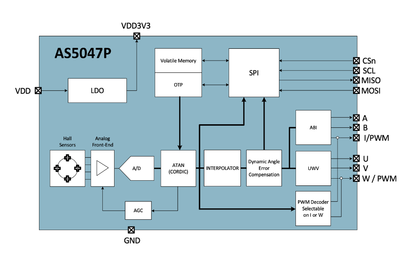
An absolute position magnetic encoder (AMS AS5047P) is used to sense the magnetic field changes induced by a magnet attached to the back shaft of the motor. This encoder communicates directly with the motor controller through ABI, since interfacing with multiple encoders through the ODrive hardware is not possible through SPI. Using ABI keeps the future option of interfacing with two encoders with a single board open. The ODrive motor controller then reads this data and determines the motor’s current absolute (rather than relative) position.
The wiring scheme of the encoder to the ODrive motor controller through ABI can be seen in this diagram in the AS5047 encoder datasheet:
The ABI quadrature interface uses three wires: A, B, and I. Connecting with the ODrive thus uses five wires, with the addition of power and ground.
To manage the position of the motor, the motor controller relies on a cascading PID control loop.
Fine tuning the PID parameters based on the behavior of the motor as read from the encoder data is essential for accurate positional control of the brushless motor. The ODrive motor controller provides a live plotter tool to chart the data from the encoder when connected via USB to a computer, which is useful to tune the ideal PID gain values. For example, a large overshoot in position beyond the desired set point would indicate that the D gain values are off, while a slow ramp-up to the desired position indicates lacking P gain values. Fine turning of this control loop would be expected to be quite difficult to get right such that positional control of the brushless motor is a balance of responsiveness, precision, and stability.
The ODrive is directly interfaced with a computer through USB, which provides a two-way communication. From the command line, the ODrive can be configured and controlled. The ODrive also reports the current position as read by the encoder, which is then plotted on a graph through the help of the liveplotter tool.
A 4S LiPo battery with a rating of 30C can be used to power the Odrive motor controller, and by extension, the motor. The battery is chosen such that the maximum current it could provide exceeds the peak current draw of the motor used.
The overall circuit would be therefore be arranged like so: The computer would interface with the ODrive motor controller through USB. The LiPo battery would be connected to the power terminals of the Odrive motor controller. The three wires of the motor would be connected to its respective terminals on the motor controller. Finally, the encoder is wired to the motor controller through a five-wire ribbon cable connected on the corresponding pins (ie A->A, 5V->5V etc.) and would interface using ABI.
Parts
SunnySky V3508 motor
- ODrive motor controller
- AS5047P encoder
- LiPo battery (4S 1000mah 30C)
Possible Challenges
- Accurate and precise positional control might be difficult to achieve with the brushless motor
- Challenges with understanding the output from the encoder and knowing how to adjust the control loop from there
- Difficulties in soldering small parts (I only have 1 solder tip)
References
[1]"madcowswe/ODrive", GitHub, 2020. [Online]. Available: https://github.com/madcowswe/ODrive. [Accessed: 19- Sep- 2020]
[2]P. Wensing, A. Wang, S. Seok, D. Otten, J. Lang and S. Kim, "Proprioceptive Actuator Design in the MIT Cheetah: Impact Mitigation and High-Bandwidth Physical Interaction for Dynamic Legged Robots", IEEE Transactions on Robotics, vol. 33, no. 3, pp. 509-522, 2017. [Accessed: 19- Sep- 2020]
[3]T. Wilkinson, "3D Printed Robot Joint with Active Compliance", Hackaday.io, 2020. [Online]. Available: https://hackaday.io/project/165653-3d-printed-robot-joint-with-active-compliance. [Accessed: 19- Sep- 2020]
[4]G. Levine, “OpenTorque Actuator,” Hackaday.io. [Online]. Available: https://hackaday.io/project/159404-opentorque-actuator. [Accessed: 27-Sep-2020].


