Addiel Martinez-Perez ECE 110 amart202
Ruian Pan ECE 110 ruianp2
Jihyun Lee ECE110 jihyunl2
Introduction
Statement of Purpose
Our design aims to add fashion and automation into the rather outdated but still effective way of transportation: the bicycle. We intend to add a keyless system that works with an infrared remote and an alarm system for the bicycle lock, making it convenient and more deterrent to theft.
Background Research
A four year undergraduate student has a 53% chance of having his or her bike stolen. [1] With such a high rate of bike theft and so many people riding bikes, improving the system and making it more convenient is very important for college students.
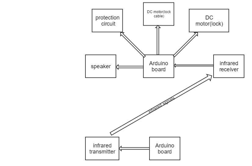
The basic structure of a car remote control system includes a CPU, an infrared light receiver and transmitter, a command module, and a pushbutton.[2] We certainly do not need something to "fire" a bicycle up, like what we do with a car, so what we basically need is a set of infrared equipment(bluetooth can also be considered), an arduino board as the CPU and the command module, a push button in the lab kit, a speaker as an alarm during emergency and a circuit designed to make the bike even safer.
Design graph
|
Design Overview
The bike lock is based on a normal bike lock–that means you can also open it in a normal way in case of an emergency.
There is a DC motor in our design, that responds to the infrared input and retracts the wire together. The infrared transmitter and receiver works to deliver message from the remote to the system. The protection circuit stays with the bike lock itself, in order to prevent the lock from being cut and the wheels from being taken off.
If resources and time permits, we also intend to create a retracting mechanism for the bike lock; that is, the bicycle will also carry a box that after the lock disengages will coil the lock's cable into the box, allowing for rapid unlocking of the bike and for faster "take off", to the destination of the user.
Possible challenges:
1.) the mechanical part of the retraction of the lock can be very tricky, we will likely need to design another locking mechanism or retrofit our design onto an existing lock
2.) the protection circuit needs to be sturdy and sensitive,
3.) the Arduino board needs to be well detected, and have a clear communication with the remote.
[1]"College students beware!," in National Bike Registry. [Online]. Available:
https://www.nationalbikeregistry.com/college.html. Accessed: Sep. 19, 2016.
[2]O. 21, "Remote keyless entry systems overview - application note - maxim," in Maxim Integrated, 2016. [Online]. Available:
https://www.maximintegrated.com/en/app-notes/index.mvp/id/1774. Accessed: Sep.
code writing update:
We spent two weeks on our code, which is supposed to ring an alarm when the wire is cut. We spent some time figuring out the tune function, and decided that our alarm will be a simple blending of two pitches going repeatedly, which is pretty annoying.
We planned on doing the trick with energy, but later we decided using digital pins is much easier. We learned about digitalRead and digitalWrite, and we successfully finished the code and the functioning within two weeks. The code has a simple logic: we define one output pin as high and we use anther pin as input and connect them. Then we detect whether it is high or low to determine whether the alarm to start making noise or not. The process takes some time though, and we will try to improve that.
We tried to do the remote part of our project with the emitter and the receiver from the lab kit, but the emitter turned out to be too weak to trigger the receiver in a distance. We later used an infrared LED to perform the task with aluminum foil (to focus the signal).
Our lock design will feature a rotating tube to be controlled by the actuator. The tube will rotate and either lock with the teeth of the "key" of the lock, or be in a position which will allow the free movement of the "key". By controlling the movement of the actuator, we will have in essence achieved remote control over our lock.
12/2/2016
TODAY we went to the machine shop with our lock design. The machine shop guys will make our lock design a reality.
