| Name | NetID | Section |
|---|---|---|
| Arnav Jaggi | ajaggi3 | ECE 120 |
| Vishesh Prasad | vprasad3 | ECE 120 |
Statement of Purpose
Our goal with this project is to create an electronic mechanism to seamlessly unlock your door using an app on your phone. Constantly carrying and worrying about your keys can be a hassle, and as everything is becoming increasingly automated and controlled through a smartphone, it only makes sense to unlock your door remotely. We will learn Arduino/Raspberry Pi, CAD, and Java to aid us in our project.
Background Research
Our background research includes looking at remote door locks that are currently on the market. Most consumer-available door locks are separate mechanisms that must be installed inside the door and don't allow customization of the door lock mechanism. Our project differs from this in that it is a separate mechanism that can be attached to any door. This will allow us to keep the cost of the total parts low as it is a smaller machine. It also allows the door mechanism to be customized. The door lock our group is working on also allows the mechanism to be moved around to different doors without much hassle, which differs from other remote locks that are fixed onto one door. Our group is driven to work on this project in order to find a solution to the problem of having to carry our dorm keys everywhere. Our thought process was to create an app and remote door lock so that we can lock and unlock the doors with the use of our phones without having to carry the key everywhere and potentially losing it.
Block Diagram / Flow Chart
Flow chart:
Start by launching the app that is connected via arduino to our mechanism. The user will then choose to lock or unlock their door (entered as input). If the input is lock we set lock to be true, and then we will set the servo to 90 degrees (so vertical), and send the completion message, terminating the program. Else, if not, we check the value of unlock. If for some reason unlock is set to false, then we will send error message. If it is set to true, we set the servo to 0 degrees (so horizontal) and send the completion message, terminating the program.
System Overview
This first image is a top view of our design. It is a little hard to see due to glare, but you can see that the Servo is coming out the back of our side. In addition, we have encased the servo in a crate like case that we will be 3-d printing. The front of said crate (bottom of picture) will be extremely thin, so as to fit in between the lock and the screws that connect it to the door. The rest of the crate will envelope the actual turning mechanism of the lock with enough space for our turn hands to fit (more on them below).
This is the front view of our design. The holes that can be seen prominently on the bottom are replicated on the top. The design is much bigger than projected, for the purposes of detail and emphasis. The holes seen are for screwing the crate to the lock. We are heavily considering changing the design to have 2 middle holes instead of 4 top and bottom.
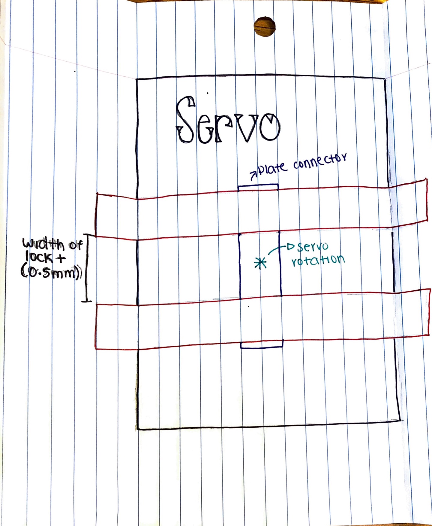
Here is the inside view of our crate, the actual turning mechanism. The hands that turn the lock are depicted in the reddish color, going horizontal in the picture. The servo is labeled, (black in the back), and the purple connector latches the hands to the servo mechanism. The servo mechanism is depicted in green.
Parts
Possible Challenges
Challenges that our group foresee in working on the project includes deciding on a power source for the door lock. We have to decide whether to use an external power source or a wired connection. We also have to come up with a design for the remote lock that is not too bulky in size while also being functional. The casing for the lock must also be rigid enough to allow the servo to properly apply the necessary force needed to turn the lock. Other challenges include being able to successfully merge the Arduino with the servo and get the motor to be fully functional. This is also combining the Arduino with the app and to be able to get a seamless connection from the hardware to the software without errors.
References
All About Circuits. 2021. Servo Motor Control with an Arduino. [online] Available at: <https://www.allaboutcircuits.com/projects/servo-motor-control-with-an-arduino/> [Accessed 20 September 2021].
Report
https://docs.google.com/document/d/1nuJlQzxX3FV1lxS0xqJwMKHxe6oJm8oaSa1ayk3r3rw/edit?usp=sharing
Remote Controlled Door Lock with App
Arnav Jaggi
Vishesh Prasad
University of Illinois at Urbana - Champaign
ECE 120 Honors Lab Report
Introduction
The goal of this project was to create an electronic mechanism to seamlessly unlock your dorm door using only an app on your phone (that we design). Constantly carrying and worrying about your keys can be a hassle, and many students living in the dorms, adjusting to college life for the first time, have shared this concern with us. As everything is becoming increasingly controlled through a smartphone, it only makes sense for you to be able to unlock your door with your phone as well.
Design
Our original design involved the following flowchart:
We wanted to have the user start by launching the app that we built, that would be connected to the arduino via a mechanism. When we started out, we didn’t know exactly what we would use for it, but we ended up coming with a concrete technique. We would connect our Arduino to our app using bluetooth or wifi, and then connect the arduino to our breadboard, which is then connected to the servo. The entire servo and breadboard system was to be powered by an external source, likely a battery.
Results
Most of our plans came through, but we had to change a little bit to make things work. We ended up buying a MKR Wifi 1010 Arduino, which has both bluetooth and wifi capabilities. We connected our servo and breadboard to a power source, with a 9V Energizer battery. We were unable to CAD the claw that would actually latch onto the lock of our door, but we did get the servo functioning completely. We started by coding our servo in the offline Arduino IDE. We then built an app, using the MIT app builder, which was complete with bluetooth capabilities, and reading and writing from and to bluetooth. We also used Xcode for an apple app but we didn’t completely develop it as we found that it doesn’t have bluetooth capability that works with the arduino. However, we were unable to completely connect the app, phone and servo, as mentioned below. We decided against putting in an LED, and switches, due to lack of functionality. Seeing as we didn’t have the CAD, and servo connection, we decided to prioritize the latter, as opposed to extra features that we would gain by adding a LED and push-button switches. In order to build our app, we had to use logic gates. We used NOT and AND gates the most. For instance, we used a NOT gate to check whether or not bluetooth is connected to the phone. We also used a lot of multidimensional if loops to control the locking and unlocking mechanism, which meant that we used advanced AND gates.
Problems and Challenges
The main challenge that we faced with this project was controlling the arduino using the app. We experimented with different types of connections (WIFI vs bluetooth). WIFI was the ideal mode of connection as the code that connects the app and the arduino is simpler and the connection is more secure. WIFI, however, didn’t work as the UIUC wifi needs authentication for a connection and the arduino doesn’t have those capabilities. We then decided to connect using low energy bluetooth. We attempted to connect to the arduino, through bluetooth, using our laptops (macbooks and windows), but these connections were sporadic and we were never able to get a constant connection. We also attempted to connect using our iPhone and android app emulators on the laptops, but these emulators didn’t have bluetooth capabilities. We then connected using our iPhones and a third party app, and were able to get a successful connection but couldn’t run the app we built as it was an android app. As a last resort we tracked down an android phone and were able to get a successful connection again through a separate third party app, but were unable to connect the phone or our own app due to unforeseen technical issues.
Future Plans
We feel as though the natural progression of our project is to first start by finding better ways to fix the connection between the servo, arduino, and phone. Once we fix up the connection issues, we will then add on the CAD of the claw, and then design a lightweight case for the entire system, so that it can be latched onto the door.
References
https://www.raywenderlich.com/2295-arduino-tutorial-integrating-bluetooth-le-and-ios
All About Circuits. 2021. Servo Motor Control with an Arduino. [online] Available at: <https://www.allaboutcircuits.com/projects/servo-motor-control-with-an-arduino/> [Accessed 20 September 2021].
Project Demo Video


