member: David Zhao, Ben Pan, Alan Cheng
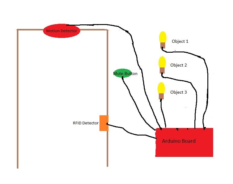
Description: Our project will be attaching a motion sensor and a RFID detector on the door of dorm room. The goal of our project is to remind student to bring the objects he/she need to carry every such as keys, icard and i clicker. The motion sensor will send out an output when a person passes through the door. We would attach RFID chips on those objects. Whenever the aduino broad recieves the output from the motion sensor and the RFID detector cannot detect the signals from RFID chips, it would command a speakor to beep in order to remind the person. We would first use different LED lights with tags of each different objects to notify the user what object he/she is missing. If possible, we want to program the adruino broad so that it will send a text message to the user about what objects he/she is missing. We will also have a button on the wall to mute the speakor. So the user can choose to leave the door, but doesnt have to pick up the stuff he need and knows what he/she doesnt have with himself/herself.
A rough sketch of our project:
Material:
SparkFun RFID Evaluation Shield - 13.56MHz(https://www.sparkfun.com/products/10406)
RFID Module - SM130 Mifare (13.56 MHz) (https://www.sparkfun.com/products/10126)
XBee 1mW Wire Antenna - Series 1 (802.15.4) (https://www.sparkfun.com/products/8665)
SparkFun XBee Explorer Regulated (https://www.sparkfun.com/products/11373)
Header - 6-pin Female (0.1", Right Angle) ( https://www.sparkfun.com/products/9429 )
Header - 6-pin Male (SMD, 0.1", Right Angle) (https://www.sparkfun.com/products/9015)
2mm 10pin XBee Header (https://www.sparkfun.com/products/10112)
2 * Arduino Stackable Header - 6 Pin (https://www.sparkfun.com/products/9280)
2 * Arduino Stackable Header - 8 Pin (https://www.sparkfun.com/products/9279)
PIR Motion Sensor (JST) (https://www.sparkfun.com/products/13285)
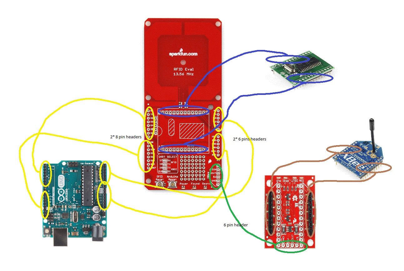
How are the components connected (Graph)
Timeline:
10/12 Schematics/ Group agreement on timeline and after class hour
10/19 Start to assemble components
10/26 Finish the build
11/2 Programming
11/9 Finish Programming ( /further implementation)
11/16 Debugging ( /further implementation)
11/23 BREAK
11/30 Test/ Debug/Final Report
12/7 Final Presentations/ Final Report
after class hour: Saturday 9:30 am - 12:00 pm (scheduled on weekly basis)
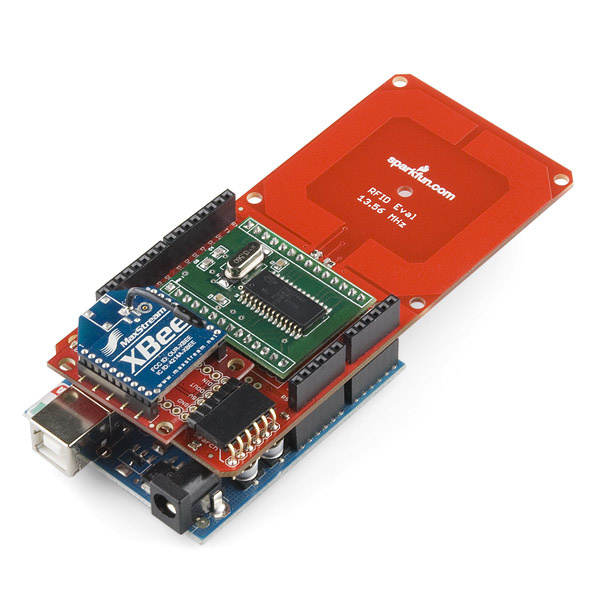
Update(10/3): We did not know about RFID before. So we watched a tutorial about RFID. After that, we started to find the material need to set up the RFID. We first looked through the start kit from sparkfun. But that one can only detect RFID chip within a very close range. We figured out that we need a RFID shield with attached antenna to detect the signal from RFID chip. We looked through the datasheet of RFID shield on sparkfun website to learn how to set up the detector. The website does not include all the components we need. We are figuring out what components are we missing currently. We will try to finalize the list next week, and plan to build our projects. Below is a image which is very helpful for us.
Update(10/5):
We searched more about the materials we need for our project. We found out that different components are connected by headers. We are not sure about the headers that we will be using in the project. If the headers we selected dont work, we will buy the right one at local stores to prevent delay of progress. Besides finalizing the material list, we made a rough sketch about how to connect each components together. There are actually several components which are needed to set up in order to detect RFID chip. The other concern about our project is that since we connect all the pins on the arduino broad to the RFID shield, we do not know which pins on the shield can be avaible for us to be used to connect other components such as motion detector and led lights to the arduino board. We need to do more research about it next week.
Update(10/12): We made group agreement on the pace of our project throughout the semester If we can't finish the project in weekly class time, we are excited to work on Saturday morning Also, we looked up on the website of the shield and found out which pins were available to be used for other components such as motion sensors and LED lights
Update (10/19):
We received the rfid shiled, xbee antenna, and motor detector today. We still need some headers to connect all the components together. So we sent out an additional component list with the headers we need to the TA. We planned to solder the rfid module to the regulator since the connection is very loose. we also talked about the basic logic for our program.
Update(10/26):
We didn't recieve the remaining part this week. If we cant get them next week, we will think about some other alternatives. Oscar helped us to solder the rfid module onto the regulator. Then we looked up the schematic for the regulator. We noticed that some pins have asterisks nearby, so we thought these pins were used by the module so other pins are free to use. Since we dont have headers to connect the arduino board to the regulator, we will test it out later. We also found sample code on the sparkfun website. We glanced through them, and would study more about it next week.
Update(11/2):
We looked up the schematic to figure out the correct orientation of the evaluation shield onto the Arduino board. One of the TAs gave us the long-pin headers to connect the two parts together. Since we are prohibited to solder by ourselves, we asked Oscar to help us to accomplish this task. He told us that he would give us the components on the open lab on Sunday. Then we studied how to program. Our goal for next week is to finish building the RFID and test out the serial number for each tag.
code:
/*
RFID Eval 13.56MHz Shield example sketch v10
Aaron Weiss, aaron at sparkfun dot com
OSHW license: http://freedomdefined.org/OSHW
works with 13.56MHz MiFare 1k tags
Based on hardware v13:
D7 -> RFID RX
D8 -> RFID TX
D9 -> XBee TX
D10 -> XBee RX
Note: RFID Reset attached to D13 (aka status LED)
Note: be sure include the SoftwareSerial lib, http://arduiniana.org/libraries/newsoftserial/
Usage: Sketch prints 'Start' and waits for a tag. When a tag is in range, the shield reads the tag,
blinks the 'Found' LED and prints the serial number of the tag to the serial port
and the XBee port.
06/04/2013 - Modified for compatibility with Arudino 1.0. Seb Madgwick.
*/
/*Start
B475EE9E
B475EE9E
B475EE4E
B475EE4E
*/
#include <SoftwareSerial.h>
SoftwareSerial rfid(7, 8);
SoftwareSerial xbee(10, 9);
//Prototypes
void check_for_notag(void);
void halt(void);
void parse(void);
void print_serial(void);
void read_serial(void);
void seek(void);
void set_flag(void);
//Global var
int flag = 0;
int Str1[11];
//INIT
//green 6, red 5
int pirPin = 2;
void setup()
{
pinMode(5, OUTPUT);
pinMode(6, OUTPUT);
pinMode(pirPin, INPUT);
Serial.begin(9600);
Serial.println("Start");
// set the data rate for the SoftwareSerial ports
xbee.begin(9600);
rfid.begin(19200);
delay(10);
halt();
}
//MAIN
void loop()
{
read_serial();
//motion detector
digitalWrite(5,LOW);
digitalWrite(6,LOW);
int pirVal = digitalRead(pirPin);
if(pirVal == LOW){ //was motion detected
Serial.println("Motion Detected");
delay(10 );
}
else
{Serial.println("66666");
delay(10 );
}
//green light
if(flag >0) {
digitalWrite(6,HIGH);
delay(3000);
digitalWrite(6, LOW);
}
if(flag == 0) {
if(pirVal == LOW)
digitalWrite(5,HIGH);
delay(3000);
}
if(flag >0 && pirVal == LOW)
Serial.println("Welcome");
}
void check_for_notag()
{
seek();
delay(10);
parse();
set_flag();
if(flag = 1){
seek();
delay(10);
parse();
}
}
void halt()
{
//Halt tag
rfid.write((uint8_t)255);
rfid.write((uint8_t)0);
rfid.write((uint8_t)1);
rfid.write((uint8_t)147);
rfid.write((uint8_t)148);
}
void parse()
{
while(rfid.available()){
if(rfid.read() == 255){
for(int i=1;i<11;i++){
Str1[i]= rfid.read();
}
}
}
}
void print_serial()
{
if(flag == 1){
//print to serial port
Serial.print(Str1[8], HEX);
Serial.print(Str1[7], HEX);
Serial.print(Str1[6], HEX);
Serial.print(Str1[5], HEX);
Serial.println();
//print to XBee module
xbee.print(Str1[8], HEX);
xbee.print(Str1[7], HEX);
xbee.print(Str1[6], HEX);
xbee.print(Str1[5], HEX);
xbee.println();
delay(100);
//check_for_notag();
}
}
void read_serial()
{
seek();
delay(10);
parse();
set_flag();
print_serial();
delay(100);
}
void seek()
{
//search for RFID tag
rfid.write((uint8_t)255);
rfid.write((uint8_t)0);
rfid.write((uint8_t)1);
rfid.write((uint8_t)130);
rfid.write((uint8_t)131);
delay(10);
}
void set_flag()
{
if(Str1[2] == 6){
flag++;
}
if(Str1[2] == 2){
flag = 0;
}
}
08/02/2016
We decide to improve our project so we need some new materials:
Sparkfun Xbee Shield (https://www.sparkfun.com/products/12847)
XBee 1mW Wire Antenna - Series 1 (802.15.4) (https://www.sparkfun.com/products/8665)
Arduino Uno R3 (https://www.sparkfun.com/products/11021)
Servo - Generic Continuous Rotation (Micro Size) (https://www.sparkfun.com/products/10189)


