Liam Ackerman(ECE 110) liamga2@illinois.edu
Laksh Goyal(ECE 120) lgoyal2@illinois.edu
Introduction
Statement of Purpose:
For this project, we will be creating a board that will scan and register colors, and play musical notes based. Markers will be the writing material, registering different octaves and note values based on the color of the marker. The board will illustrate a graph with spaces for colors to fill in. The purpose of this is to simplify the process of writing music for composers, as well as introduce the skill to younger audiences.
Background Research:
We have done research on how color sensors work. Previous projects that employed color sensors usually had the stationary while some device would move the scanned object past it. The reason why we want to work on this project is because Liam is quite interested in music, and Laksh thought that this idea could be a useful tool. So far we have yet to find a project identical to ours, however there are a few devices that allow you to play music based on color, however in their case they are playing music directly of color, with not regard to tempo or size of note, while in our case we pay special attention to scale and to the various different types of music. We aren't able to generate chords though without more rigorous experience in coding and building.
Design Details
Block Diagram / Flow Chart:
System Overview:
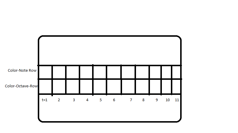
The first diagram shown is a layout of the board. The board would have two rows in the middle, and multiple columns inside those rose, making empty spaces. The user would color in the top and bottom rows using markers, and each different combination will create a new note. There would be a scanner suspended above the board, and it will sense the colors from left to right while motors are sliding it across. The Color sensors will take a value each, and that combination of values will go through the Arduino midi and produce a sound. This means that coloring a portion of the board a single color will produce a long-lasting note, so both color and spacing matters. The board will have a setting for bpm(beats-per-minute), and changing the bpm will make use of a logic gate that will input different voltages to the motors depending on how fast the use wants the scan to read and play the notes.
Parts
- 2 Motors(Ordered)
- 2 conveyer belts
- A whiteboard
- Markers
- Logic Chips(IC's)
- Wooden Base
- Breadboard
- Microcontroller(Received MSP-430)
- Wooden Block(To build the frame)
- Wires (Undisclosed amount)
- Color Sensors - 2(Ordered)
Possible Challenges
Some challenges could be making it more intuitive for users. Another could be how to ensure that the music writer isn't disturbed by the presence these electronics. Coding these responses onto the breadboard will also be very difficult.
References
Data Sheets
Color Sensor
https://media.digikey.com/pdf/Data%20Sheets/DFRobot%20PDFs/SEN0101_Web.pdf
MSP-430
http://www.ti.com/microcontrollers/msp430-ultra-low-power-mcus/overview.html
Energia(Software)
Midi
https://www.arduino.cc/en/Tutorial/AnalogToMidi
Final Report

