1a. Introduction
This project is to build a refrigerator that is based on the thermoelectric effect using commercial Peltier modules. The internal size and shape of the refrigerator is to be a cube of 0.5 meters with a door on top that gravity holds shut (maybe with some weak magnets if needed for cooling performance). The primary problem that this refrigerator is to solve is to be very durable and long-lasting as a practical way to refrigerate the stated quantity of items even compared to commercial refrigerators. This means that it is very important to respect the power limits (and such) of all components, to have a reasonably modular and repairable design, and to have food-grade materials for the internal part of the refrigerator. It would be quite unfortunate if some toxic compound ended up in food (in the worst case, food grade 3D printer filament exists that may be useful). Lastly, it is very important to me that I get to keep this refrigerator, in its fully functional form with all parts, at the end of the class. If this means that I must make some design changes and/or pay for some of the less expensive parts then that is fine. Unfortunately, paying for the entire thing myself is not possible (this is the primary reason that I haven’t already made it).
1b. Background Research
As part of my background research, I did several things: 1) watch as many YouTube videos that I can find showcasing similar projects (see the references section for the highlights, but this has been something that I have wanted to do since before I was aware of the honors lab, so I didn’t keep a full list), 2) research, in detail, how Peltier modules work (again, highlights in references, but it isn’t an exhaustive list), 3) discussions with a professor about how to build a constant current source, and 4) I attempted, and, so far, failed to do a calculation for how much cooling capacity is needed in order to appropriately design the Peltier module. Due to the inefficiency of Peltier-based systems, compared to compressors, it is worth considering some relatively exotic insulation options (primarily, aerogel). Aerogel is a relatively new material and has the best insulating properties of any known solid, but it is also somewhat more expensive than alternatives (e.g. styrofoam). It is commonly used in cryogenic applications, outdoor pipes, and for efficiency in high temperature applications. Whether aerogel or the cheaper styrofoam is preferable is best decided by calculating the reduction in Peltier module capacity and power consumption based on it, to determine if it provides a net cost benefit or detriment.
2. Block Diagram & System Overview
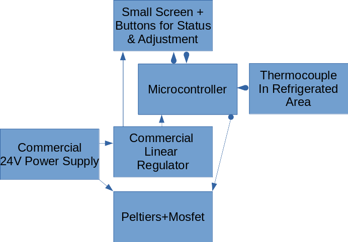
The plain arrows represent power. The arrows with a rounded base represent information/signal lines. The “small screen” is a simple alarm clock style display that can show the current temperature and target temperature, while the buttons can adjust the target temperature. The goal is to get that information out as cheaply as possible. Putting wifi + an HTTP server on the Arduino is another option (I could easily write the HTTP server, I have done so before, albeit not on a microcontroller) if that turns out to be cheaper (it seems like the digital screens are surprisingly expensive). The code on the microcontroller won’t be a full PID control loop, but will rather communicate a specific current to the mosfet that controls the Peltiers that is proportional to the temperature difference between the target and current temperature. With adequate capacity, it should reach an equilibrium that is very close but slightly to the target temperature where the heat that gets pumped out is almost exactly equal to the amount of heat that is let in through the insulation. Ideally, this will mostly be contained in a PCB to allow for it to be cleanly organized and stable (soldered together), with PCB bus bars for the high current parts.
3. Parts
Screen
Buttons
Microcontroller
Thermocouple
Linear regulator
24V power supply
Peltier(s)
High current mosfet or IGBT
Wood to build the frame (I am very open to advice for how to better accomplish this, but I don’t want to use a pre-made refrigeration frame (e.g. no cooler, no broken refrigerator))
Insulation (aerogel or styrofoam)
Misc. electronic parts
PCB
PCB bus bars
3D printed enclosure for PCB, or perhaps a plastic case with holes punched in it for buttons, the screen, wires to Peltier, etc.
4. Possible Challenges
Keeping cost under control
Efficiency
Safety (24V can be dangerous)
Construction of the physical frame (I have very little experience in this regard)
5. References
Aerogel: https://thermtest.com/applications/aerogel-thermal-conductivity-hfm
Peltier: https://www.youtube.com/watch?v=cw8ipUYodkE, https://www.youtube.com/watch?v=RkSR4rTl2GY, https://www.youtube.com/watch?v=YWUhwmmZa7A
More Peltier: https://www.cuidevices.com/blog/how-to-design-a-peltier-module-system