- Introduction
- This project will include the creation of a video game controller-type machine that, with certain inputs, will make a character perform specific actions on a makeshift video game. The goal overall is to make a fully functioning set of inputs in a controller that uses digital logic and gates to produce certain outputs. The circuitry should be able to fit in a 3D printed controller mold that can be held and have the functionality of a video game controller. An Arduino program will be able to handle the processing of inputs to outputs from the controller to the game. If possible, we would want to let the controller be able to connect to a system of some sort, as a wired controller would. This will make our project unique due to how practical the use of a controller can be and how it can be done with minimal resources.
- In ECE 110, we've had some experience with logic gates and how they can work in a circuit. Using microcontrollers, we can use the knowledge obtained in 120 to produce the outputs that we want. To add, we have played video games so we'd know the expectations regarding how the controller should generally work.
- This project will include the creation of a video game controller-type machine that, with certain inputs, will make a character perform specific actions on a makeshift video game. The goal overall is to make a fully functioning set of inputs in a controller that uses digital logic and gates to produce certain outputs. The circuitry should be able to fit in a 3D printed controller mold that can be held and have the functionality of a video game controller. An Arduino program will be able to handle the processing of inputs to outputs from the controller to the game. If possible, we would want to let the controller be able to connect to a system of some sort, as a wired controller would. This will make our project unique due to how practical the use of a controller can be and how it can be done with minimal resources.
- Design Details
- Block Diagram / Flow Chart
- System Overview
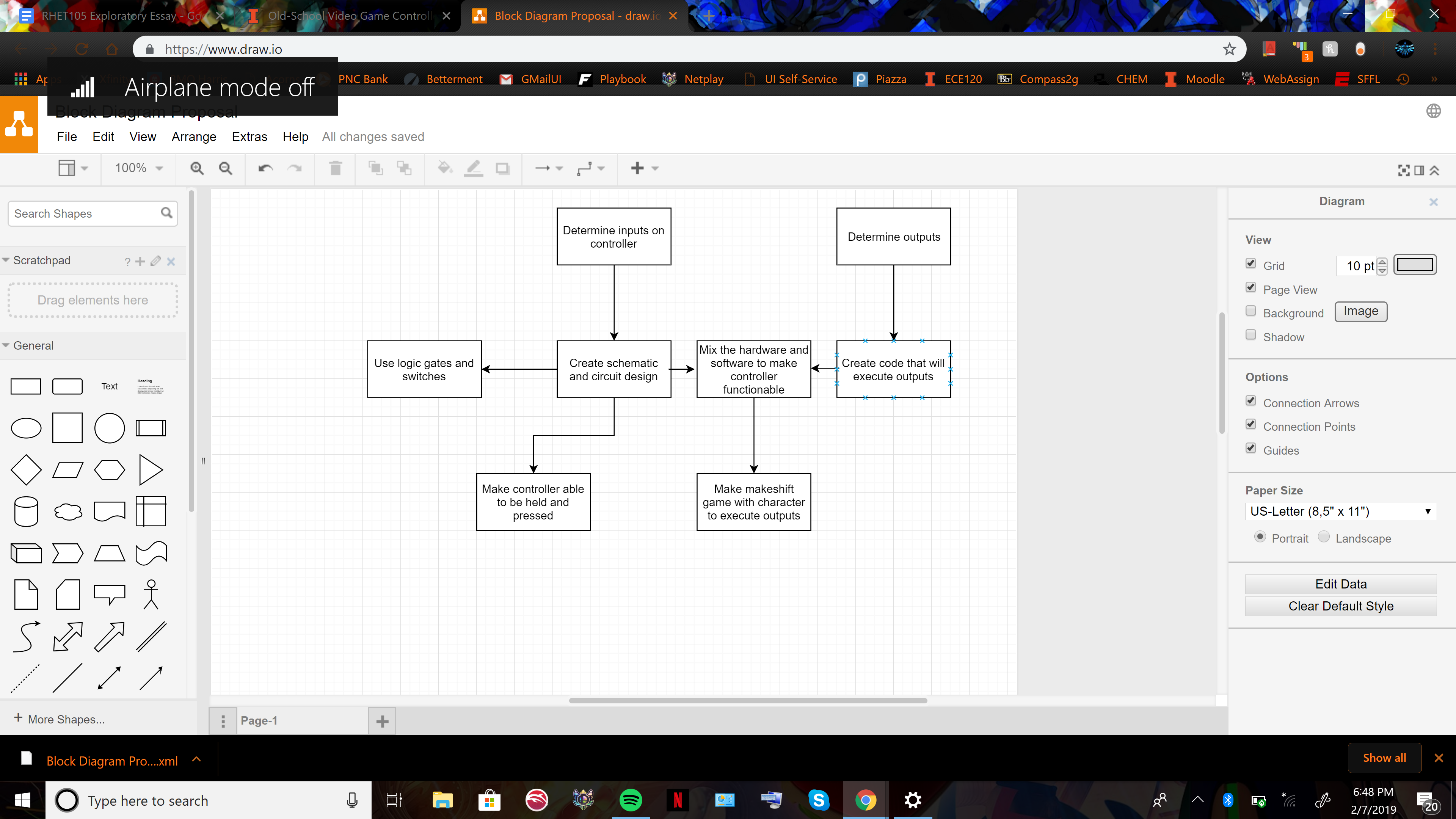
We will start by determining exactly what the controller will do, including the inputs and the outputs. The functions that the controller will have to carry out will determine our entire project, so that will be step 1. Next, we can get into either the hardware or software side. For hardware, we would create the schematic and what the circuit will look like using logic gates and switches, along with carrying out the function of a controller by making it handheld and able to be pressed. For software, we will need to create code that determines what the outputs will be from the inputs pressed by the controller. By connecting the two, programming will need to be done to create a makeshift game with a character that can execute the outputs. - Random Notes (Not set in stone)
- We can set up a restriction that wouldn't allow a player press certain buttons at the same time, such as up and down or left and right, but allow other buttons to be pressed at the same time, like up and right etc. Also, pressing more than two buttons at once wouldn't be allowed. This would be achieved using different logic gates, such as NAND and NOT.
- We can also set up a force sensor on the buttons to determine how hard a player presses a button. Functionally, this can be used to either make the character in the game jump really high if the jump button is pressed hard or jump only a little high if pressed lightly.
- Another possibility to fulfill the logic/sensor element is to use a comparator in order to create ranges for the force sensor to work in. Rather than using an Arduino, a comparator is a hardware-based element that can directly tell the force sensor which inputs would function in different ranges based on how hard the button is pressed.
- Making a wire that connects from the controller to a USB Port - Parameters
- Up, Down, Left, Right (D-Pad)
- Force sensors on D-Pad (light press and hard press)
- 3 regular buttons
- Start button
- Wire to USB Port
- No shoulder buttons
- Handles
- Resembles Genesis controller the most, with PS1-like shell
- Block Diagram / Flow Chart
- Parts
- Logic gates
- Breadboard
- 3D printed controller shell
- Buttons
- Arduino
- Force Sensor
- Wire to connect to a USB Port - Possible Challenges
- Programming the game will be tough since it's a little outside the scope of the lab
- Determining what logic gates and specifically what coding we need to be using for the controller to function
- Completing the circuit/Connecting logic gates to the switches
- Fitting the circuit into the controller shell - References
“Designing Game Controls.” Gamasutra Article, www.gamasutra.com/blogs/AndrewDotsenko/20170329/294676/Designing_Game_Controls.php
Instructables. “Making a USB Game Controller.” Instructables.com, Instructables, 13 Oct. 2017, www.instructables.com/id/Making-a-USB-Game-Controller/
Deuskar, Tanmay. “Video Game Controller With Arduino.” Instructables.com, Instructables, 31 July 2017, www.instructables.com/id/Video-Game-Controller-With-Arduino/
Team, EFY. “Make Your Controllers for Any Game Using Arduino.” Open Source For You, 11 Sept. 2018, opensourceforu.com/2017/07/make-controllers-game-using-arduino-diy/
Instructables. “Interfacing Force Sensitive Resistor to Arduino.” Instructables.com, Instructables, 22 Aug. 2017, www.instructables.com/id/Interfacing-Force-Sensitive-Resistor-to-Arduino/.
Marco Rojas - marcor2
Ritesh Reddy- rareddy2
Lingxiao Mou - lmou2

