| Name | NetID | Section |
|---|---|---|
| Wesley Vong | wvong2 | ECE 120 |
Statement of Purpose
The purpose of this project is to design a digital music synthesizer from scratch. At this point, a majority of the music synthesizer's core engine is completed but the UI is inadequate. In this lab, I aim to upgrade the UI such that the user can experience the power of the synth engine in an easy and efficient way. The current UI hardware consists of 16 LEDs and 19 Tactile switches. The LEDs are currently able to provide limited feedback to the user and the switches let the user access different features in the synthesizer. The switches as of now is adequate but the LEDs are insufficient for the synthesizer as it makes the UI very complex and confusing. To upgrade the UI, I will add a graphic display to effectively communicate the synthesizer's status to the user, more LEDs to clearly indicate simple information, and add shift registers for buttons, to reduce the amount of pins used.
Goals:
- Add a graphic OLED display to the synth
- Add more LEDs on the synth
- Add shift registers for buttons instead of assigning a button per pin
- Design a pleasing and easy to use UI
- Ensure performance is not severely impacted
Background Research
The synthesizer's motivation is based on the lack of innovation in the music synthesizer space. Most synthesizers on the market revolve around the same four core concepts, subtractive synthesis, wavetable synthesis, fm synthesis, and sample flipping. Although these concepts are very powerful, it is getting boring. I want to create a synthesizer with a unique and complex synth engine.
As the synth engine is getting more complex, the existing 16 LEDs is not enough to effectively indicate all the information to the user. In addition to that, the current system of controlling LED brightness using software causes an increase in CPU overhead, crippling the performance of the synth engine. Through internet research, I have decided on offloading the led brightness control to a dedicated IC and add a display to clearly convey information to the user.
There are two main display types on the market, TFT (Thin Film Transistor) and OLED (Organic LED) displays. To find the optimal display, I looked at the comparison between these two types of display. TFT displays are generally cheaper and have higher resolutions compared to OLEDs. However, OLEDs have much higher contrast, better viewing angles, and can have lower power draw. Since I want the synthesizer to have a clear display where resolution does not matter much, I decided to add an OLED display instead of a TFT display
While there are other audio synthesis related products, this project is unique in focusing on the UI aspect of the synthesizer. This project intends to allow the user to effectively communicate to the synthesizer and vice versa as the core synth engine is already complete.
Block Diagram / Flow Chart
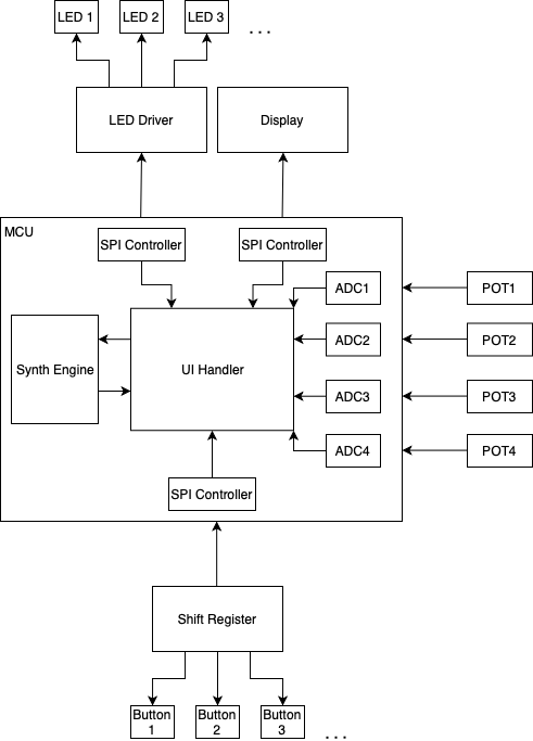
Made from draw.io
System Overview
The block diagram shows the data flow for the synthesizer. There will be four human interface elements, potentiometers (labeled POTx), LEDs (labeled LEDx), Buttons (leveled Buttonx), and the display. The buttons and LEDs will be controlled by an external IC which is then interfaced with the MCU via its hardware SPI controllers. The pots are directly connected to the microcontroller's analog to digital converters (ADCs). All of this is then passed into the software UI handler which reads the input data and sends all the output data. The UI handler also communicates with the synth engine.
Parts
Provide a list of parts that you may need for your project. You should include details such as the quantity, model number, purpose, vendor, and price (excluding taxes and shipping) for each part. This list may change as you work on your project.
| Part | Description | Quantity | Unit Price | Source |
|---|---|---|---|---|
| TLC5955DCAR | 48 Channel LED driver with PWM | 1 | $6.53 | Digikey |
MDOB256064D1Y-WS | 256 * 64 pixel 2.08" OLED | 1 | $29.27 | Newark |
| M74HC165TTR | SMT 8 bit Parallel to Serial Shift Register | 3 | $0.32 | Digikey |
| CI1110M1VR0-NH | JST SH style 10 pin header | 2 | $0.33 | Digikey |
| CS11025.0F160 | SMT SPST Tactile Switch | 19/20 | $0.24 | Digikey |
| PCB + SMT | PCB + Some surface mounting | 1 | N/A | JLCPCB |
Possible Challenges
Since the synthesizer is not programmed using Arduino, standard Arduino libraries for driving the display will not work. As such, I will either have to create my own driver, or port Arduino libraries to my IDE.
Minimizing the impact of this upgrade on computing power would be challenging given that the MCU has to drive a display.
This project involves designing a friendly UI. Since I have little UI experience, I would find this challenging.
Demo
Report
Wesley Vong
ECE 120 Honors Lab
Final Report
12/10/21
Group #17 Music Synthesizer
Introduction
This project aims to improve the existing UI on a music synthesizer I have been working on. The existing system consists of 19 buttons and 16 leds. As the synthesizer gets progressively more complex, the 16 leds prove to be the bottleneck in developing an intuitive UI. The new UI hardware should include a display to show relevant information to the user in addition to more leds.
Design
The design consists of adding an OLED display, a LED driver IC, and button shift registers. By using shift registers and dedicated ICs, the MCU now only uses serial data to communicate with the peripherals. This is in contrast to the existing design where every LED and every button is hardwired to a certain pin on the microcontroller. A serialized design reduces the pin count on the microcontroller and allows for much simpler UI revisions in the future. The protocol used for every peripheral on the UI board is SPI. This is because SPI is simple to implement, fast, and is controlled through onboard hardware on the MCU. This means data transmission from the MCU to the peripherals can be offloaded, allowing more processing time for the synthesizer engine.
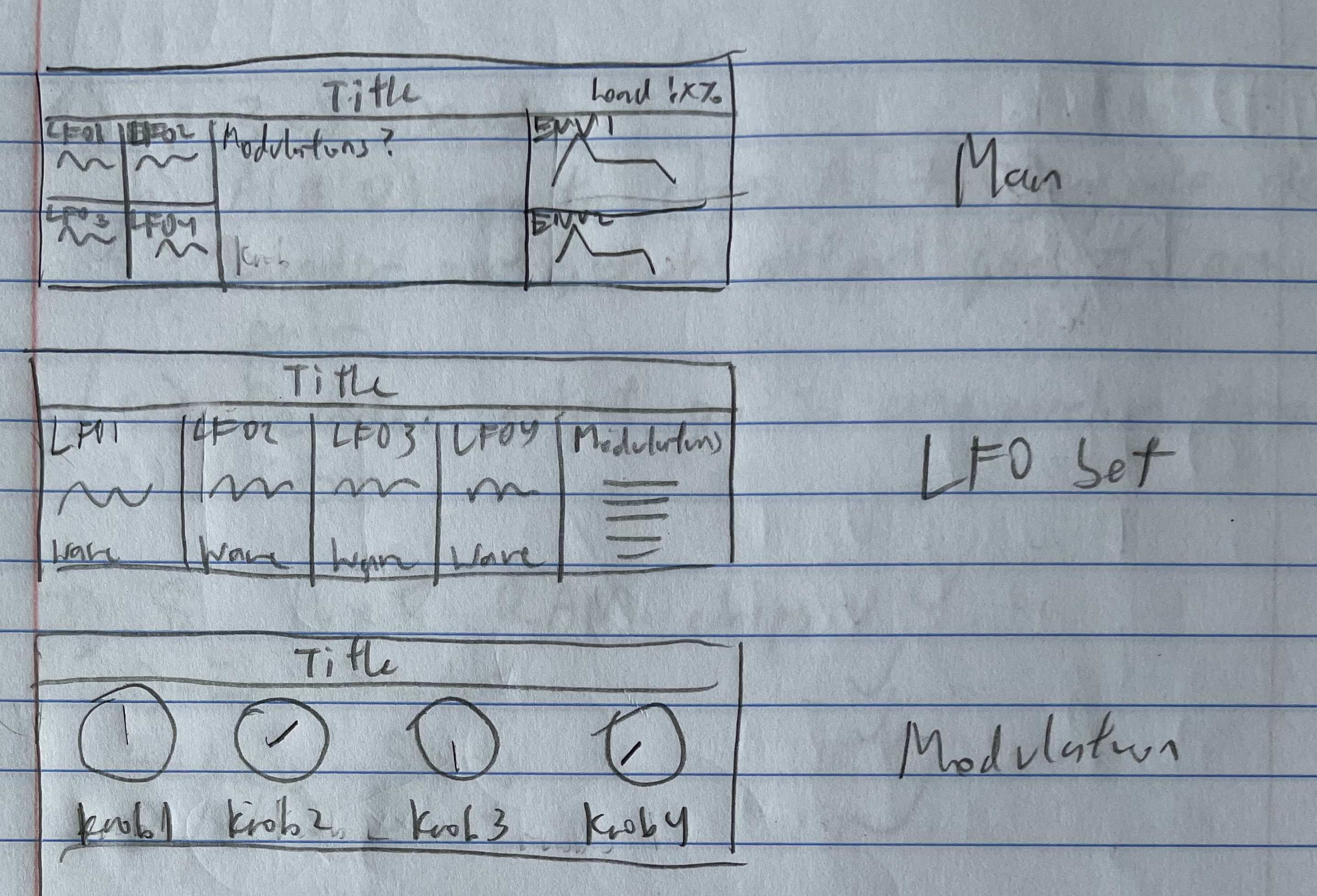
Above are a few early designs for the UI for the OLED display. These exact designs were not used in the new UI, but did provide some inspiration for the final display UI.
Results
The final design uses a 256x64 pixel monochrome OLED display, a LED Driver IC, and three parallel in serial out shift registers for the keyboard. All of these ICs are driven by two of the microcontroller’s SPI busses. The OLED display gets its own SPI bus while the LED and keyboard shift registers share one bus.
Because the microcontroller I am using, an STM32, is not arduino compatible, I cannot use standard Arduino libraries to drive these peripheral ICs. Therefore I wrote my own libraries to drive the peripherals. When developing the libraries, I noticed a few issues with the design. Firstly, the shared SPI bus between the keyboard and LED ICs caused issues where both ICs ended up sending data on the same data line simultaneously. I fixed this by cutting the PCB trace connecting to the output of the LED driver. Secondly, running two SPI buses led to interference which made the display unreadable. To fix this, I added some pull down resistors to the display’s SPI clock lines.
Above is the layout of the new PCB. The Keyboard and LED ICs are located on the bottom of the board to reduce PCB size. The OLED is placed on the top side of the board. Note that the OLED display is not level because it is not soldered directly onto the PCB, instead placed into a pin header. Below is the new UI in the current state. The display and LEDs updates based on context. Although not shown here, the buttons work as expected as well with the exception of the top left button. This is because the top left button is not wired to the keyboard shift register, instead wired directly to the microcontroller.
Problems and Challenges:
Some challenges encountered when updating the UI include incorrect PCB wiring, unclean signals, and complex implementation of SPI on certain parts.
The first iteration of the new PCB consists of a major hardware issue where the keyboard buttons are wired incorrectly. This prompted a second revision of the PCB. This fixed the major button wiring issue but still had some signal fighting issues stated in the results section.
Unclean signals proved to be a major issue in the new UI. The OLED display and LED driver consumes significant power which makes the power supply less clean. This affected the sound output of the synthesizer by adding unwanted noise. The use of two spi busses and long wires connecting them to the top board also lead to noise in the SPI data lines. This caused the OLED display to flash. I added two 10k pull down resistors to the SPI clock pin which solved the problem.
Finally, as stated in the results section, I created my own libraries for the display, keyboard, and led. The display and led driver proved to be challenging to program. The display had 4 bits of brightness control, meaning every pixel on the display is 4 bits. Since the SPI data is 8 bits long, I had to do some bit manipulation to write to the display. The led driver had a similar problem, where the SPI data length is 8 bits, but commands range from 1 bit to 7 bits long.
Future Plans
I plan to create another revision for the PCB, fixing any remaining issues I found. I also plan to finish developing the UI for the synthesizer. The current ui is merely a placeholder and I intend to make the ui more useful for the user.
Reference:
[1]"6 synthesis methods in a nutshell", MusicRadar, 2009. [Online]. Available: https://www.musicradar.com/tuition/tech/6-synthesis-methods-in-a-nutshell-196545. [Accessed: 16- Sep- 2021].
[2]"TFT Display VS OLED Display", Stoneitech.com, 2021. [Online]. Available: https://www.stoneitech.com/news/sharing/tft-display-vs-oled-display.html. [Accessed: 20- Sep- 2021].
References
[1]"6 synthesis methods in a nutshell", MusicRadar, 2009. [Online]. Available: https://www.musicradar.com/tuition/tech/6-synthesis-methods-in-a-nutshell-196545. [Accessed: 16- Sep- 2021].
[2]"TFT Display VS OLED Display", Stoneitech.com, 2021. [Online]. Available: https://www.stoneitech.com/news/sharing/tft-display-vs-oled-display.html. [Accessed: 20- Sep- 2021].

