| Name | NetID | Section |
|---|---|---|
| Shomik Chatterjee | shomikc2 | ECE 120 |
| Matthew Pianfetti | mcp6 | ECE 120 |
Final Project Report + Video
Final Circuit Diagram
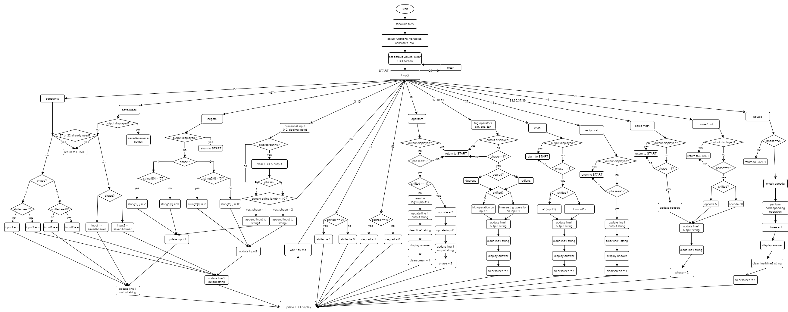
Final Code Flowchart
Updates
4/27
- started coding and assembling device
- got all the numbers, equals, plus, and clear to work
4/30
- added decimal point and minus
- added conversion to scientific notation for large/small numbers
5/1
- added multiply, divide
- added exponent, root, shift
- added negate
- added save/recall
- added log (pt. 1)
- added log (pt. 2)
5/3
- added trig functions
- added constants
- added reciprocal
- fixed some issues with printing values
- added degree/radian shift
5/4
- rearranged device for ease of use
5/6
- finished report
Initial Project Proposal
Statement of Purpose
There is no bigger flex than showing up to a test in a class with an obscenely large and only semi-functional calculator. We are aiming to create such a calculator using a microcontroller for the main processing unit.
Background Research
Originally, we were going to pursue a project along the lines of Ben Eater's 8-bit computer. However, we decided instead to pursue making a calculator. Calculators are often thought of as simple devices, but they are essential to our everyday lives.
Research we have done includes and is likely limited to:
extensive use of a calculator to figure out how we are going to replicate its features
going over various datasheets to determine how to get inputs into the arduino
One other reason that we chose to pursue this project is because Arduinos use a modified version of C, which is a language taught in ECE 120.
Block Diagram / Flow Chart
Basic Block Diagram:
Sample Flowcharts for inputs:
Circuit Schematic:
System Overview
Hardware: The user gives inputs to the arduino in the form of pressing buttons. The inputs are displayed on the LCD Screen. Once the proper number of inputs have been given, they are run through the software on the Arduino. Once a result is calculated, the final output is displayed on the LCD Screen.
Software: We will write the code ourselves.
The calculator will operate in two phases. The current phase of the calculator will help the calculator determine what to do when inputs are pressed (e.g. which string to append digits to, what to print to display, what string to clear, etc.)
When receiving a numerical input, the calculator will store this information in a string. When necessary, this string will be converted to a float for calculations. A string is easier to store data in because numbers can be appended and removed much easier.
When an operator is pressed, the calculator will determine which operator it is, since each operation we plan to implement will be mapped to a certain integer.
Operator Code Table:
| INTEGER | OPERATOR |
|---|---|
| 0 | "+" |
| 1 | "-" |
| 2 | "x" |
| 3 | "/" |
| 4/400 | exponent/root |
| 5/500 | log/10^ |
| 6/600 | ln/e^ |
| 7/700 | sin/arcsin |
| 8/800 | cos/arccos |
| 9/900 | tan/arctan |
| 10/1000 | store/recall |
The shift button will modify the operation integer; this allows us to save space by halving the amount of buttons required for operators.
Parts
PCB Momentary Tact Push Buttons Switch x26 Used to take user input. $3.97
USB Type B 2.0 to Type A x1 Used to connect Arduino to computer $7.99
LCD Display CFAH2004A-TMI-JT x1 Used for displaying I/O $14.48
Mega 2560 x1 Takes inputs, runs the program, and gives outputs $13.99
Power supply x1 Gives the Mega 2560 power $7.99
Possible Challenges
Displaying inputs and outputs onto the LCD Display
Making effective use of space
Effectively communicating ideas between the two of us due to the distance
Coding the program to calculate and print results
References
[1]"Arduino Button Tutorial Using Arduino DigitalRead Function", Arduino Project Hub, 2021. [Online]. Available: https://create.arduino.cc/projecthub/muhammad-aqib/arduino-button-tutorial-using-arduino-digitalread-function-08adb5#:~:text=Just%20connect%20the%205V%20from,through%20the%20220%20ohm%20resistor. [Accessed: 19- Feb- 2021].
[2]Robotshop.com, 2021. [Online]. Available: https://www.robotshop.com/media/files/pdf/arduinomega2560datasheet.pdf. [Accessed: 19- Feb- 2021].
[3]Crystalfontz.com, 2021. [Online]. Available: https://www.crystalfontz.com/products/document/437/CFAH2004A-TMI-JTDatasheet.pdf. [Accessed: 19- Feb- 2021].

