| Name | NetID | Section |
|---|---|---|
| David Gong | dsgong3 | ECE 110 |
| Jaelynn Abdullah | jja8 | ECE 110 |
Statement of Purpose
Create an MPE controller with keyboard action and capacitive touch sensors on each key. One problem with other MPE controllers I have seen is that although they are more expressive, they seem harder to play precisely. This project combines expression using capacitive sensors with ease of playability of piano action.
Background Research
MIDI is a protocol that allows electronic instruments to communicate to each other. Recently, there has been a new protocol that uses MIDI called MPE. MPE (Midi Polyphonic Expression) uses the MIDI protocol in a way that allows each individual note to have greater expression through more dimensions of control. In normal MIDI, most of the controls are global and applied to all notes. With MPE, however, each note has its own channel. So, each note can have all its parameters such as volume, pitch bend, timbre, etc. controlled independently.
Our idea is to implement capacitive sensors to a keybed and program multi-dimension control over each key using an Arduino, transforming it into our own personal MPE. With the sensors, we can begin to utilize MPE-like functions such as aftertouch, pitch, and velocity.
There are a few projects similar to ours, namely the TouchKeys. They used capacitive sensors that can sense x-y movement and capacitance through finger surface area and sell DIY and preinstalled options. Our project has a smaller scope than the TouchKeys and is also more affordable.
Block Diagram / Flow Chart
Hardware
Software
System Overview
Hardware
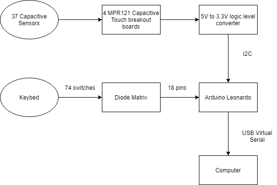
In order to get capacitive sensors to work with the Keybed, we are using a 12-key Adafruit MPR121. From there, the 5V to 3.3V logic level converter and the 12C bus will allow the breakout boards and Arduino to receive information from the sensors after user input.
From the keybed, just like how other microcontrollers and keyboards, the 74 switches will be connected to the diode matrix to isolate signals coming from the keybed. The 18 wires coming from the diode matrix will then be connected to the 18 pins on the Arduino board to receive input from the keybed.
Each key of the keybed is equipped with two contacts that switch "on" one after another. The time between the first and second contact is used to calculate the Midi velocity. There are 74 wires for 37 keys. All the switches are then run through a diode matrix for 18 wires.
The MPR121 has an address pin that allows four different addresses. They can then all be connected as slave devices to the Arduino’s SCL and SDA pins.
Software
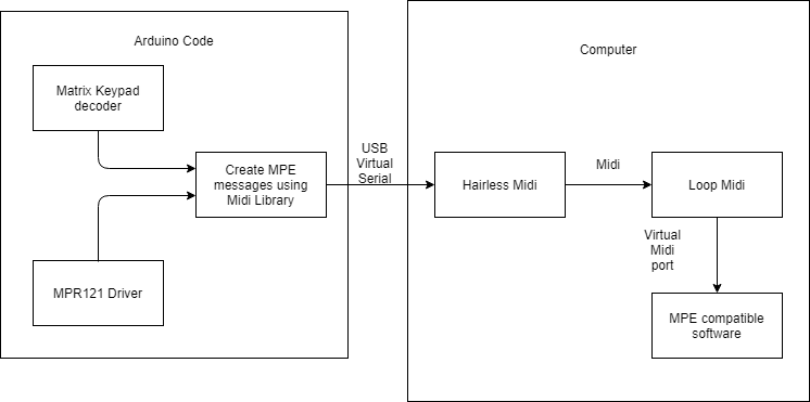
The software is broken up into two components, the programming and then the computer interface. For the coding, the Arduino will have to take input from the diode matrix and information from the MPR121 breakout boards so the data can be processed and then create MIDI messages. The algorithms will be based on an online, open-source, midi library.
Then, for the computer portion, the hairless midi will read in the midi signals, which is then pushed onto to loop midi, which will connect the midi signals from the hairless midi to the MPE software, where that midi signals will finally correspond to sound based on the time between switches being turned on or off, how long the switch is pressed down before, and where the finger is located on the sensor.
There already is a library for matrix style keypads for Arduino that supports multi-keypresses. There is also an Arduino library for the MPR121. Both are well documented with examples and compatible with our Arduino.
Parts
Name | Quantity | Link | Price excluding shipping and tax ($) | Comments |
Keybed 37 keys | 1 | 59.95 | Need to talk to staff about buying from non-approved vendor. | |
Arduino Uno | 1 |
|
| We need a microcontroller w/ at least 18 digital I/O pins. Uno has 14 digital and 6 analog which can be used as digital. I already have one. |
MPR121 | 4 | 6.95 | Breakout board for capacitive sensors. We need four because each board supports 12 sensors and we need 37 sensors. This board has built in 3.3 to 5v logic level conversion. | |
Copper Tape |
|
|
| Lab already has it |
Possible Challenges
The major challenge I foresee is writing software. Currently, there are no Arduino or C++ libraries for creating MPE messages in the way that we want. We will have to modify an existing midi library to generate MPE messages. This will be difficult because we will have to get into the nitty-gritty documentation of MPE and neither of our programming skills is that great.
Final Deliverables
References
Ilett, J., 2015. 1-Day Project: MPR121 Capacitive Touch Sensor Music Organ. [online] Youtube.com. Available at: <https://www.youtube.com/watch?v=AhVizoU8CB4> [Accessed 14 September 2021].
Docs.juce.com. 2015. JUCE: Tutorial: Understanding MPE zones. [online] Available at: <https://docs.juce.com/master/tutorial_mpe_zones.html> [Accessed 14 September 2021].

