Today we researched the ideas about detecting a bike lock being cut and the materials necessary to detect such a breach. We looked into a circuit that would be able to detect when it was open and then trigger the alarm. We found we could do so using an inverter gate. We decided that the best way to make an alarm would be to have the alarm on the bike not the lock - that way the bike cannot simply be taken away from the alarm (which is on the cut lock). Therefore, we will need the circuit on the lock to send a signal of some sort to a separate system on the bike. We believe this could be done with a Bluetooth ping between two Arduinos. We are also looking into ways to notify the system that the user is there so it ignores the lock being taken off. Additionally we are considering the fact that U-style bike locks are two pieces which presents a challenge with having a circuit around the lock. We will look into the possibilities for how to deal with this such as two circuits or another solution.
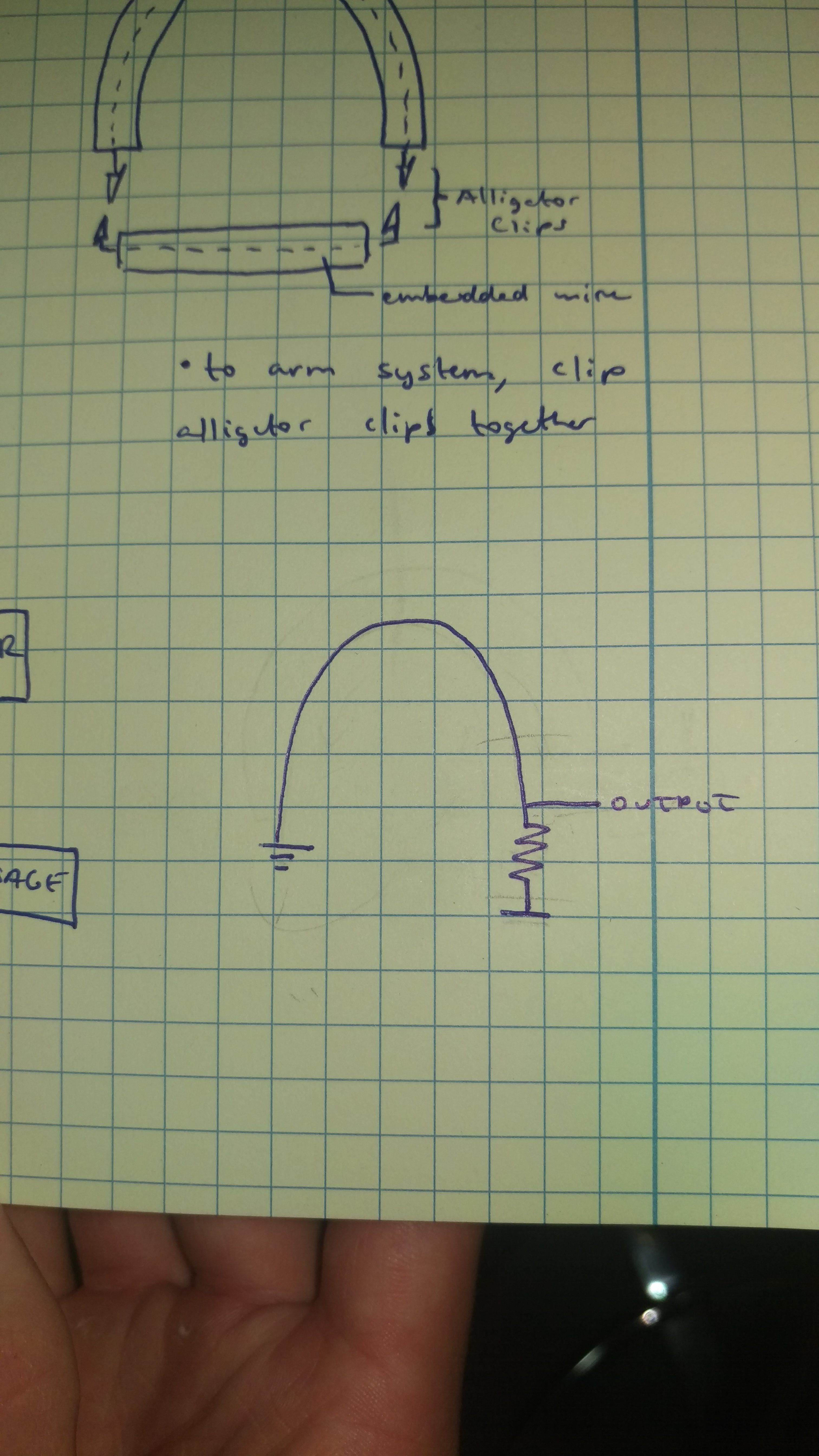
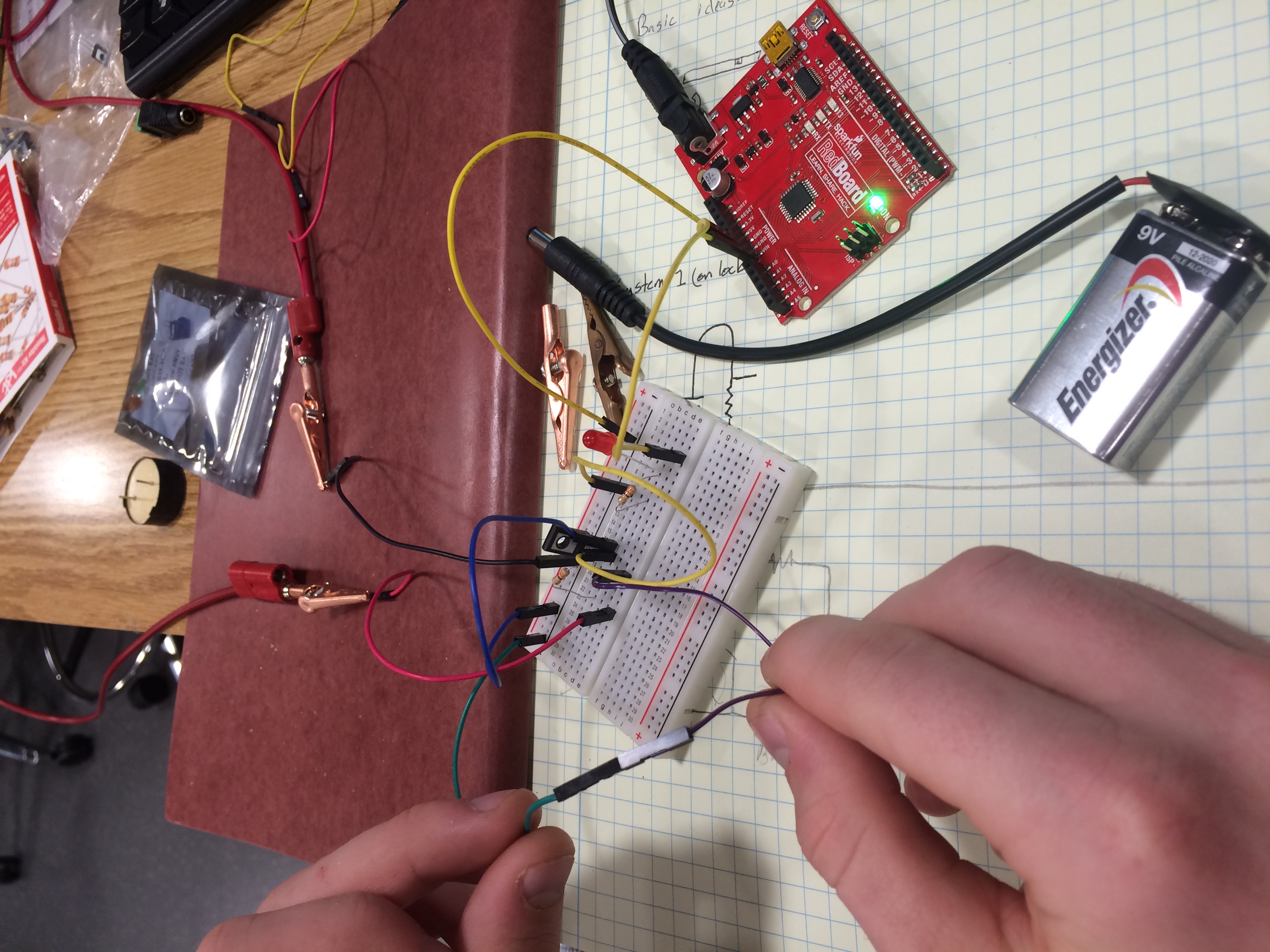
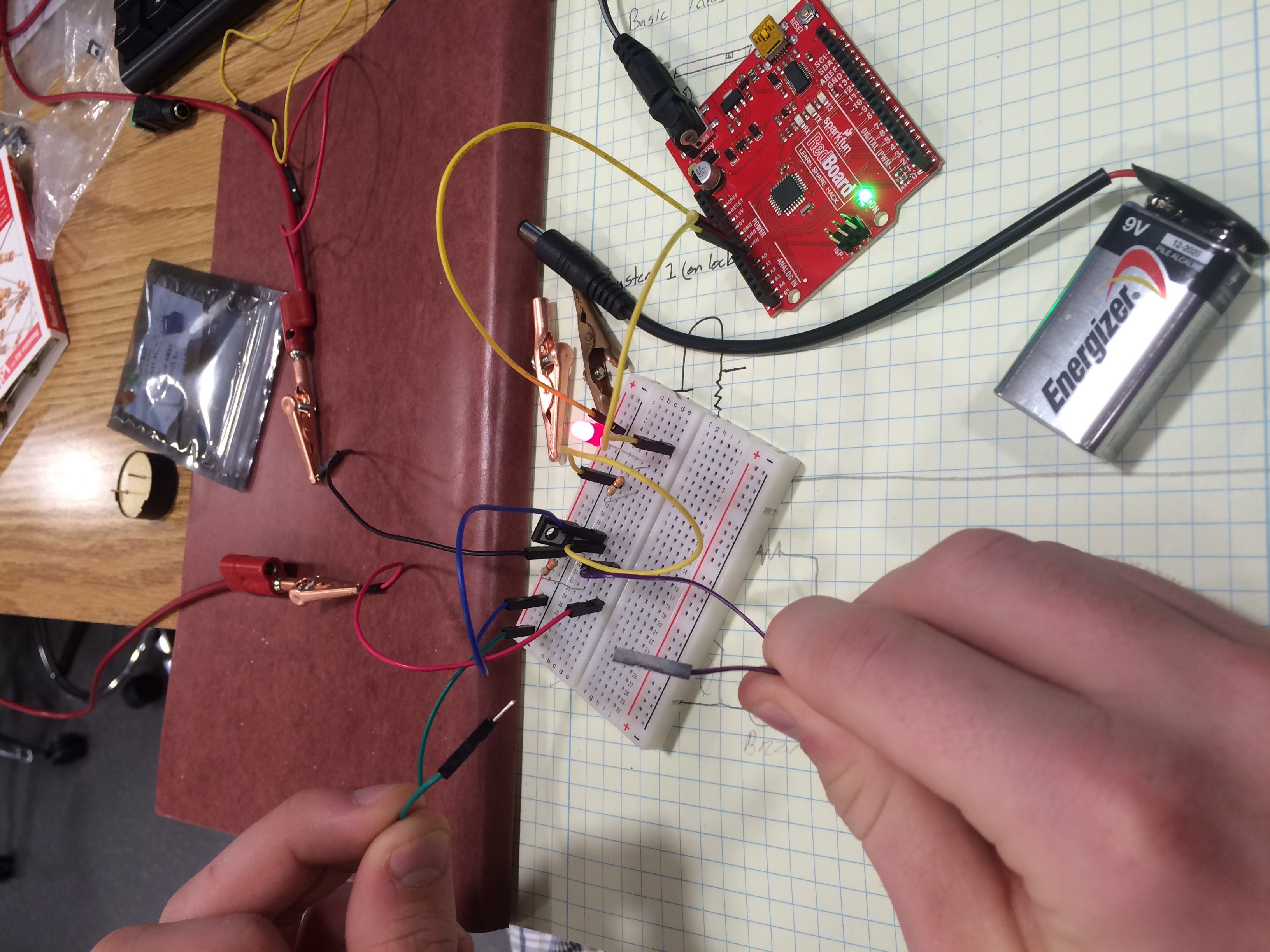
Today we looked into the circuit that will be used to detect the bike lock being cut. The current plan for the circuit has been inserted above in section 1b. The circuit will basically be a voltage source, a resistor, an output, and a ground. We made a model of the circuit using a bread board. When the direct line to to the ground cut the voltage of the output decreased to zero from five volts when there was a direct line to ground. We will be able to use this drop in voltage to determine if the lock has been cut or not and then take the appropriate action. At this time we are still looking into how we will have an override for the owner so that the alarm will not trigger when the owner wants to unlock their bike.
Today we made low level circuit drawings and determined different parts we needed and researched said parts. This included piezo buzzers and DC to DC converters. We still have not determined how we will get the circuit on the bike to tell the buzzer on the bike to go off or how we will have an owner override.
Today we researched different methods for communication between the system and the owner of the bike. We researched Wifi, Cellular connection, and NFC methods for wireless communication. We will investigate the launchpad system for coding and implementation of the SMS. We also looked into the possibility of two separate systems on the bike, or just one hardwired system. Modified the parts list to incorporate the launchpad system, and we found a code hub for the production of complicated code using the launchpad system.
Today we simplified the system. The project goal was shifted from absolute prevention to considering the economics of the project - we will no longer use a launchpad. A simple transistor and circuit will be used. This will make the system much cheaper and smaller so that it fits in the bike and is in general more viable.
Today we tested the lab kit's buzzer in an oscillating circuit to see how the buzzer reacts to different frequencies and voltages. We also built a prototype circuit with a transistor, and the buzzer was producing a sound even when the base of the transistor did not have a voltage across it, so we will need to re-build the circuit and figure out what is going wrong next week. We will also re-send an e-mail to Oscar with the parts list so that we can begin testing the components for our final circuit. Then we can begin testing for the ideal resistances and voltages so that our circuit works optimally within the bike lock.
Today we built a working proof of concept. The proof of concept has an LED in place of the buzzer - we do not have the buzzer yet and will need to tailor the circuit to work with it once we have it next week. Below in the new prototype section is a demo of our proof of concept.
Today we used our actual parts to make a prototype of the final system. We experimented with the buzzer to determine how we should supply it. We are still considering an oscillating circuit, but at this point a constant voltage and thus constant sound is the likely path. From here we will work on the final product casing and put the entire project together on the perf board.
Today we soldered together our final version. Over the weekend at the extra lab section we designed our layout on the perf board to prepare to solder the board. We did the soldering today for most of the parts. A few of the parts are remaining to be soldered together once we have the container we are going to put the final system in.
Today we debugged and tested our circuit. At first our circuit did not work. We found that one of our solders was not good and will need to be redone at the extra lab sessions this week.


