Water Display
| Name | NetID | Section |
|---|---|---|
| Aniketh Rayudu | arayudu2 | ECE 110 |
| Patrick Marschoun | ppm6 | ECE 120 |
| Ritvik Gandesiri | ritvikg2 | ECE 110 & 120 |
| Jeffrey Chang | jdchang3 | ECE 120 |
Project Proposal Guideline
- Introduction
- Statement of Purpose
Our project involves creating a row of valves that can be individually opened and closed to let the water drops fall. By carefully controlling each valve, we would be able to represent different letters and digits using the falling water. - Background Research
Our project draws inspiration from the Water Clock at Osaka Station in Japan, a fountain built by Koei Industry in March 2011. [4] We wanted to recreate this light display because it provides us a solid balance between art and engineering to create our first project in our college engineering careers. Recreating the whole fountain may be too ambitious for one semester's worth of work, so we decided to scale down the display to a manageable number of valves in order to display smaller images and/or numbers.
To program the microcontroller, it's pretty simple. Using arrays to represent each row of drops, we can build arrays inside arrays, using 1s and 0s to build an image. Water elongation shouldn't be a huge problem. If it does happen to be an issue, however, we can figure out a way to lengthen the amount of time the valves are open for per row. We can use the number of rows in each array to use a time equation with the acceleration of gravity. Then pause for each new picture, that way the time doesn't increase to a ridiculous amount.
- Statement of Purpose
- Design Details
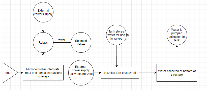
- Block Diagram / Flow Chart
- System Overview
- Relay: provides external power to the solenoid valve.
- Microcontroller: controls data and sends signals to solenoids
- Solenoid Valves: Allows opens and closes water flow
- External Power Source: powers solenoid valves
- Water Pump: pushes water back up to the tank
- Block Diagram / Flow Chart
Parts
- Possible Challenges
Some possible challenges that we could encounter would be getting enough valves to create digits from the falling water. The type and amount of characters that we can display will be limited by the number of valves we have. A big problem will be calibration of all the valves. We need to ensure that all the valves have the same water exit velocity or else the water won't fall evenly. We also don't know how fast the water will exit the valves at so that will hinder our ability to write the program that will control the valves. Another problem that we might encounter is the solenoids not opening and closing fast enough to create an image. - References
Solenoid info
- relay info
- inspiration
[1]Tinker & Build, Arduino Solenoid Valve Circuit: How to control water flow with an Arduino. 2017 [Online]. Available: https://www.youtube.com/watch?v=ioSYlxHlYdI&feature=youtu.be&ab_channel=Tinker%26Build. [Accessed: 17- Sep- 2020]
[2]Tinker & Build, How to use an Arduino Relay Module. 2018 [Online]. Available: https://www.youtube.com/watch?v=0BNcI8jMcXE&feature=youtu.be&ab_channel=Tinker%26Build. [Accessed: 17- Sep- 2020]
[3]JapanFilms, Osaka Station City Water Fountain Clock | 水の時計. 2013 [Online]. Available: http://youtube.com/watch?v=eSjuwsOjUIE. [Accessed: 17- Sep- 2020]
[4]T. Hornyak, "Osaka Station fountain displays time, art in water", CNET, 2011. [Online]. Available: https://www.cnet.com/news/osaka-station-fountain-displays-time-art-in-water/. [Accessed: 17- Sep- 2020]
