Week of Sept 26
We began to examine what parts we will need. It appears that our original plan of implementing Bluetooth to transmit data is not necessary. It will make our project more complicated and require more power. Instead, we can communicate wirelessly through the XBee chips in the same way but with a much more effective power usage. The XBee can also be connected to an arduino via an XBee shield.
The ADXL377 3-axis accelerometer has a range of +/-200g. Many concussive impacts seem to be sustained around 60g, while many hits from sports like football clock in at 190+g. Being able to measure a larger range is more realistic for the goal of this project. The accelerometer has analog outputs, which can be converted to digital if need be because the XBee supports ADC (analog-to-digital conversion), or the analog signals can just pass through as is.
We will also connect a small breadboard with the logic gate and LED to the arduino.
Week of Oct 3
We decided that it would not be practical to have wireless communication between the accelerameter and the arduino at this preliminary stage. We will have the arduino process the analog signals from the accelerometer and compute a magnitue of the acceleration. We will then use a 2:4 decoder to light up a LED that corresponds to the severity of the acceleration.
Week of Oct 10
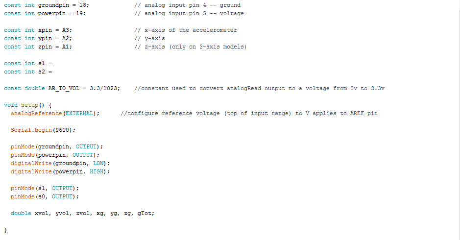
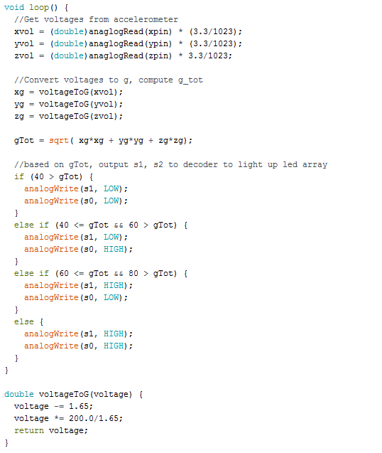
We began to write the arduino code for processing the data from the accelerometer. We based our code off of the example ADXL33 code provided by arduino. Since the accelerometer is 3.3V, we will need to set the reference of the arduino at 3.3 instead of 5 in order to ensure our calculations are accurate. We also need to convert the 10-bit integer read by the arduino into the actual voltage values in order to calculate the magnitude and compare it to our predetermined threshold values of 40g, 60g, and 80g. Since the arduino will be constantly reading in values of the accelerometer, currently it will also constantly output values to the LEDs. One issue to discuss next week is how long an LED should stay lit after a dangerous value of acceleration is detected, and if/how the code will continue to run or if it should exit afterwards. We also discussed possibly saving the output value of the decoder into a flip-flop to retain it.
Arduino code as of 10-10-16:
Week of Oct 17
Today we collected some of our parts, including the accelerometer, breadboard, wiring kit, logic gates, and resistors. We are still waiting on an arduino. We have our final first draft of the arduino code completed. We need to be able to set the high analog read on the arduino to 3.3V instead of 5V, so we are finding the correct combination of resistors to allow 3.3V to pass through.
We began to assemble our breadboard.
In order to address the issue of how long a light should stay lit after that level of acceleration is detected, we decided we will keep the same light lit until a higher level of acceleration is detected, at which point that new light will stay lit.
Week of Oct 24
Today we acquired an arduino and LEDs and finished assembling the breadboard that contains the output logic for our decoder.
Week of Oct 31
Today we wired our accelerometer on a separate breadboard and attached it to the arduino based on the diagrams given at https://learn.adafruit.com/adafruit-analog-accelerometer-breakouts/wiring. The wiring accounts for an appropriate 3.3V input for the reference pin on the arduino, so that solves one problem we were struggling with. We attempted to use the provided calibration arduino sketch to calibrate our accelerometer and find the specific range for our individual accelerometer, since there is a slight variance with each one. However, there was a problem uploading the sketch to our board so we will have to trouble shoot this issue next week.
Week of Nov 7
We soldered the accelerometer to the breakout pins to secure the connections today. We successfully were able to read values from the accelerometer. Now we need to adjust our code to properly manipulate the values based on the calibration and offset of our individual accelerometer. We also might want to modify our breadboard with the accelerometer in order to make it easier to move it around without wires coming unattached.
Week of Nov 14
Today we finished our code to correctly calibrate the accelerometer and account for offset. We also tested our output logic by lowering the thresholds to 1g, 2g, 3g, and 4g, which are easily simulated just by moving the accelerometer with our hands.
After doing some research, we decided that attempting to move to a wireless system was too complicated to attempt before the end of the semester. Instead, we think the next step might be getting a PCB for the accelerometer unit that would make it more secure to test so there aren't pieces flying off of a breadboard.
Week of Nov 21
No class due to break
Week of Nov 28
After careful consideration, we have decided that we have accomplished our goals for this semester. Our accelerometer is functional, the arduino accurately processes the information and calculates the G-force, and our output logic provides a basic alert system via the LEDs. We plan to continue our project next semester and move forward with our plans to make the accelerometer component wireless. Today, after reviewing our future goals, we began to write our Final Report.
Week of Dec 5
Today we planned our presentation and wrapped up writing our final report.


