Introduction
Ryan Slade - rdslade2 (ECE110)
Srikanth Yaganti - syagan2 (ECE120)
Statement of Purpose
Many devices in our dorms and homes are powered by AC. Our goal is to create a device that can control the powering on and off of the devices in a simple way (such as a clap). We hope to create a unit that provides power to an Arduino that will act as the switch and deliever power from a wall outlet to a variety of devices. This circuitry has the potential to provide a useful and unique interface between people and their AC devices.
Background Research
We have done a previous project that controls the motors of an autonomous car using claps. We did not have enough time to learn how to completley control this device, so this new project acts as an extension and furthering of understanding of our previous knowledge.
Design Details
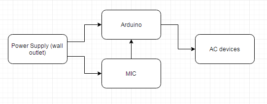
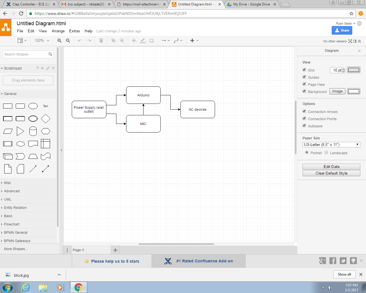
Block Diagram

System Overview
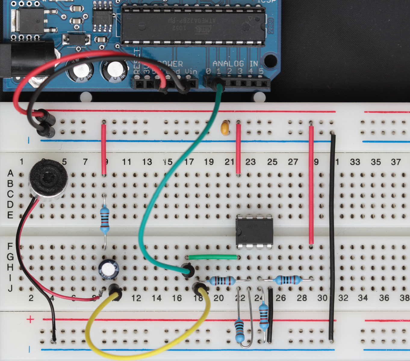
The basis of this project is the microphone sensor. This sensor is powered by a wall outlet and is used to detect user input. This signal picked up by the microphone is amplified by a transistor and sent to the analog in pin of the Arduino.
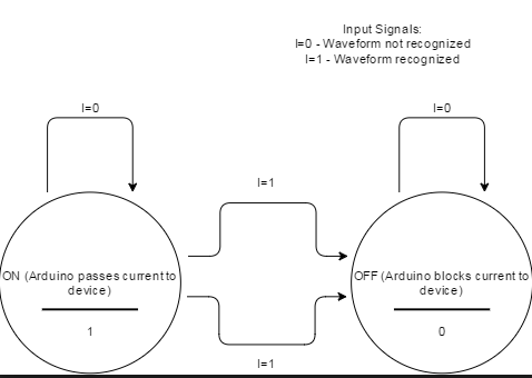
The Arduino acts as a 'gate' between the wall outlet and the devices the user wants to power. When the Arudino receives the amplified signal from the microphone, it will analyze it to see if it matches the frequency and pattern of a predetermined waveform (e.g. 'double clap'). When this pattern is triggered, the Arudino will switch between two different states of a simple FSM (ON and OFF). See below for the FSM and digital circuit.
Parts
-Arduino
-Amplified Microphone - Electret Microphone Amplifier Adafruit
-Transistor for amplification
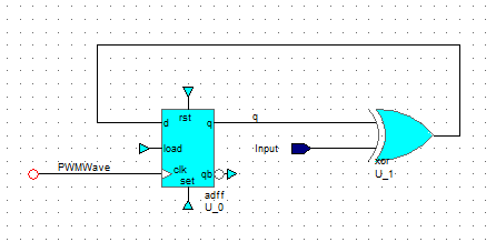
Digital Circuit:
-D Flip Flop
-NAND Gates
Possible Challenges
Recognizing the sound pattern for the clapping may be difficult. Working with the waveform recognition is touched in the video link at the bottom and we will base this portion of the circuit on the code referenced in the video.
References