Automated Watering System
Name | NetID | Section |
Ramsey van der Meer | ramseyv2 | ECE 110 |
Faye He | xh40 | ECE 110 |
Statement of Purpose
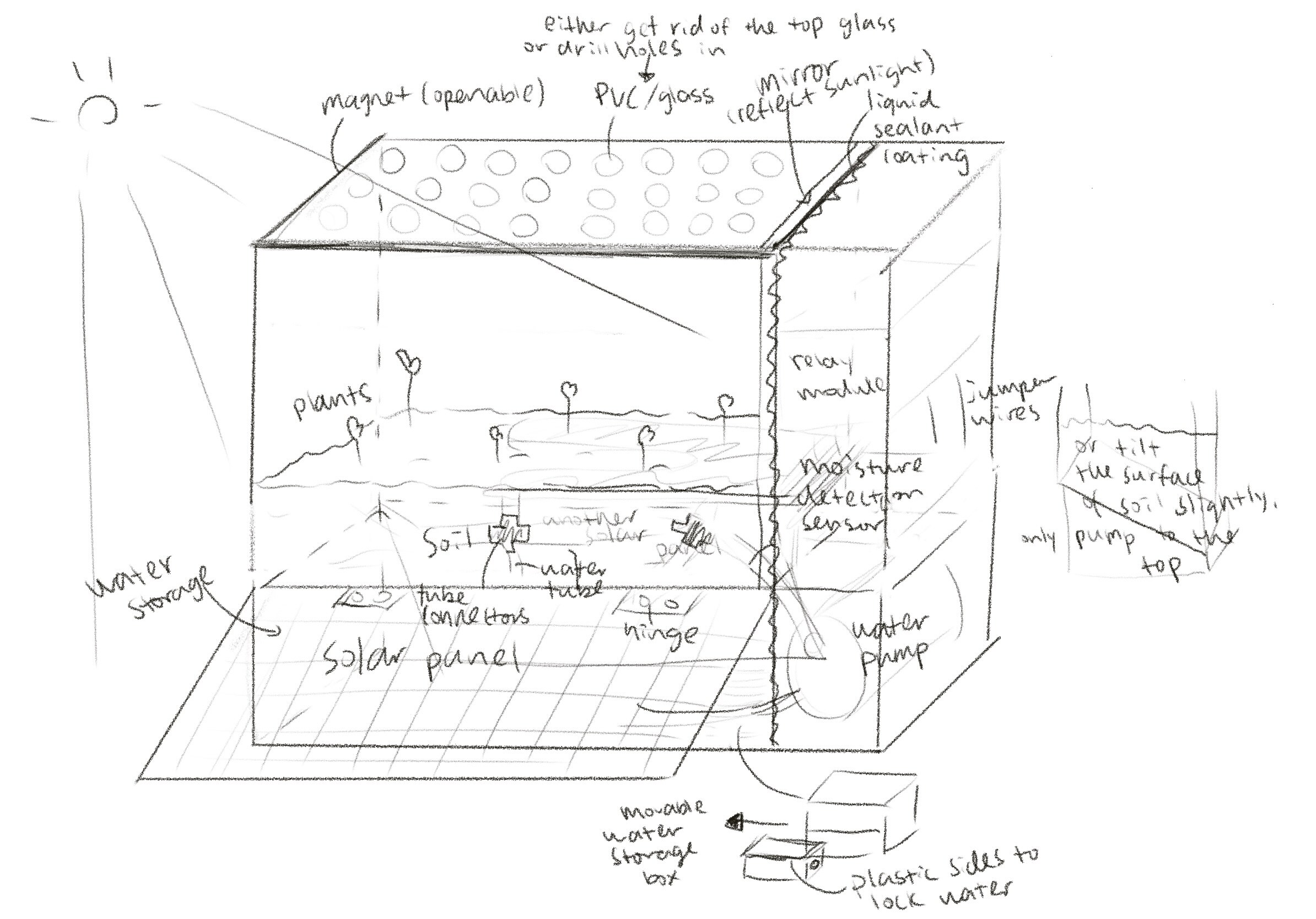
We are attempting to create a system that will automatically water a plant when the soil dries up. To make this unique we will add a solar panel so that it can operate away from a power outlet. This will be useful for home gardeners who are forgetful to water their plants or when they go on vacation and can’t tend to their plants. Our spin on this project will help allow this system to be placed away from an outlet and can be put anywhere in a yard that is exposed to the sun (literally anywhere a plant is because they need sun to grow).
Background Research
There are many Automated Plant Watering systems preexisting on the internet. All rely on the basic principle that the resistivity of the soil will go up as the soil dries. At some point where the voltage drops below a certain threshold, a predetermined action will trigger, and the system will activate.
Our group is interested in this project because we both like gardening and through this project we will be able to enjoy the fun of watching our plants grow without the tediousness of having to water them every day!
In terms of our solar circuit, we learned we will need to implement an MPPT which will optimize the match between our solar output and our power bank.
Block Diagram / Flow Chart
System Overview
Provide descriptions to your block diagram and flow chart. State the purpose of each block.
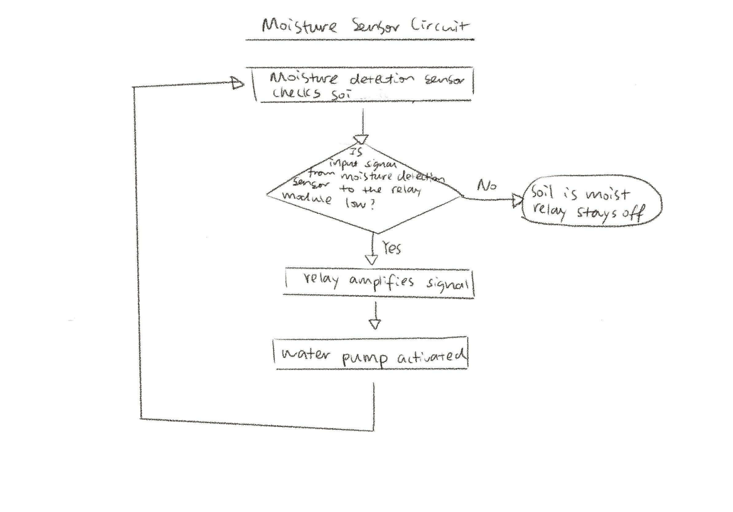
We will have a main circuit which will read the resistivity of the soil. From here it will understand if the soil is dry or not and proceed accordingly. If it is resistive that means the soil is dry since current can flow through water better than dry dirt. If this is the case the circuit will trigger the relay allowing for power to flow to the pump. Once the circuit detects that the current is following thought the soil again it will close the relay and stop the watering. In order to refute voltage for the 3V pump from the 3.7V Lipo we will use linear regulators. Also to charge our battery we will have to use a MPPT.
*Linear regulators
Parts
Provide a list of parts that you may need for your project. You should include details such as the quantity, model number, purpose, vendor, and price (excluding taxes and shipping) for each part. This list may change as you work on your project.
NAME | QUANTITY | MODEL # | PURPOSE | VENDOR | PRICE |
Electrical | |||||
Wires | lots | - | Connect components | ECE store |
|
Breadboard | 1 | - | prototype | ECE store |
|
resistors | lots | - | Regulate our voltage | ECE store |
|
Water pump | 1 | - | Pump water to plants | $2.95 | |
Relay | 1 | - | Switch on and off pump | https://www.microcenter.com/product/486581/inland-2-channel-5v-relay-module | $3.99 |
Soil Moisture Sensor | 1 | - | See if soil is dry | $8.50 | |
Arduino | 1 | nano | Logic of our system | ECE store | $12.50 |
Solar Pannel | 1 | - | Charge backup battery + power circuit | $29.00 | |
Lipo | 1 | - | Backup power for circuit | $9.95 | |
MPPT | 1 |
| Voltage regulation for charging Lipo | $9.95 | |
Agricultural | |||||
Soil | 1 | Item #93762 Model #75678300 | To grow plants | https://www.lowes.com/pd/Miracle-Gro-All-Purpose-Potting-Mix-50-Quart-Potting-Soil-Mix/999990016 or UIUC | $5.38/ 8 quarts
Free if taken from UIUC |
Plant | 1 | Item #2772188 Model #466185.199.905202 | Plant | Options Ferry-Morse 175 Milligram(s) Painted Daisy Single Mixed Colors Flower Seeds
|
$ 1.99
$ 4.48
$ 7.48
$ 1.99 |
Tube | 2 | - | Carry water | https://www.adafruit.com/product/4545
| $1.50 * 2 |
Light | 4 | Product Code: 2182 | Provide light |
| $ 0.27 * 4 |
Structural | |||||
Acrylic plastic sheet | 1 | Thickness: 1/32’’ Size: 24’’ x 24’’ | The main component of the box |
| $ 10.5 |
Hinge | 1 set (comes with 15) | SKU: DUB119 | To support the solar panel |
| $ 6.60 |
Magnet | 1 | Part #: thr-222 | Connect the box and create an openable lid |
| $ 1.99 |
Sealant | 1 | - | Prevent water leakage to electronic parts |
| $ 1.47 |
Possible Challenges
I don’t know if this will affect our results but what we are trying to do is to compare voltages and since both the resistance and the current are variable, they in combination will affect voltage. We thought that the wires in the soil would just affect the resistivity and not the current. But we will see.
Another challenge is that we will have to integrate a solar circuit into our system. This will be hard as we will have to stabilize out voltage when charging out battery. In our research we realized we will need to implement an MPPT circuit and will be hard to implement.
One thing we considered was power and if we had enough to run our system. Our battery is 1200mAh and our component will draw 103.83mA meaning we will have around 11.5 hours of run time on our lipo. Additionally, our solar panel will output 2 watts at 6V of power which is 333mA and therefore would be enough to keep the lipo charged and for the whole day and not run out at night.
References
https://www.nutsvolts.com/questions-and-answers/led-voltmeter
https://circuitdigest.com/electronic-circuits/lm3914-voltmeter-circuit
https://bestengineeringprojects.com/automatic-plant-watering-system-circuit/
https://www.youtube.com/watch?v=2r2qqi77cmQ&t=228s
https://www.solar-electric.com/learning-center/mppt-solar-charge-controllers.html/
https://learn.adafruit.com/adafruit-bonsai-buckaroo
____________________________________________________________________________________________________________________________________
Automated Watering System
Ramsey van der Meer, Faye He
University of Illinois at Urbana Champaign
ECE 110 Honors Lab
December 5, 2021
Introduction
We are attempting to create a system that will automatically water a plant when the soil dries up. To make this unique we will add a solar panel so that it can operate away from a power outlet. This will be useful for home gardeners who are forgetful to water their plants or when they go on vacation and can’t tend to their plants. Our spin on this project will help allow this system to be placed away from an outlet and can be put anywhere in a yard that is exposed to the sun (literally anywhere a plant is because they need the sun to grow).
See Appendix 1
Design
System Overview
See Appendix 2
Design Details
When designing our system we had to make the power delivery a must as our power source was variable and the components each and specific input voltages necessary. Another necessary consideration was the load that they would draw as the Arduino could only supply up to 15 mA while the pump needed 100mA to run. As such we had the regulated output of the lipo charger powering the pump behind a relay that would activate when the soil got dry enough.
See Appendix 3
Here is a diagram showing the connections between our components.
Below I have attached the logic code.
See Appendix 4
Above we are declaring the pins we will be using to read and write from and the variable sensorValue which will be overwritten by the moisture sensor.
See Appendix 5
Above is the initialization code that will run on startup. Here it sets the baud rate to 9600 and declares pinOut defined above as an output pin.
See Appendix 6
Above is our main loop which will loop infinitely as long as there is power. This will see if the sensorValue has reached a threshold of 1000 and then turn on the relay in turn running the pump. Else it will do nothing and just keep the output pin on low.
Results
We were able to get our system working but without our water pump. This was verified because we were able to see our relay switch modes when the moisture sensor got dry enough (seen in the arduino serial port with System.println()). Another way we verified our results was to use our ohmmeter to measure the load that our system pulled and was measured to be around 9mA on standby and 160mA when the relay was active and powering the pump at an assumed 100mA. Additionally, we get a voltage out of about 4V into the water pump. These measurements indicate that our solar charging system would be sufficient at powering the system overnight since the pump would not be running for the majority of the time.
Problems and Challenges
One of the problems we faced is uploading code to the Arduino software. We tried using the example code from Arduino to test if our setup is correct and we also researched to find out the issue. Lastly, we solve the problem by downloading a separate Arduino Nano Every package. While working on our project we found that our water pump was defective and we weren’t able to add a crucial part of our system. Other than that we were able to overcome the fact that the arduino nano which we initially intended to use ran on 5V by swapping this out for the Arduino pro mini which was able to run off of 3.3+V and is able to be supplied by the lipo battery. This was a challenge as we had to work through lots of driver issues in order to get this microcontroller running.
Future plans
Most pressing thing we would do in the future would be to get a working motor in the system as it was quite a bummer when we were finally able to test our system when everything else worked and our motor didn’t. We verified it was broken by supplying the motor with Scopy which could deliver the datasheet specified 3V and 100 mA and it still didn’t work. In the future we would like to replace our microcontroller for analog components since this would allow our system to consume less power. This is possible by taking the analogue output of the moisture sensor and checking if its high enough and once it is triggering the relay and allowing the pump to water the plant.
References
https://www.nutsvolts.com/questions-and-answers/led-voltmeter
https://circuitdigest.com/electronic-circuits/lm3914-voltmeter-circuit
https://bestengineeringprojects.com/automatic-plant-watering-system-circuit/
https://www.youtube.com/watch?v=2r2qqi77cmQ&t=228s
https://www.solar-electric.com/learning-center/mppt-solar-charge-controllers.html/
https://learn.adafruit.com/adafruit-bonsai-buckaroo
Appendix
PROJECT DEMO VIDEO LINK
https://drive.google.com/file/d/1hn9Dm07ccDivfjAv2JmpSFdvettwdvM3/view?usp=sharing

