Works on the Flickered Light System with Variable Resistors
By Jianqiao Xiao
Succeeded in making the lights flickering, we move on further to make the light on and off according to the light in the environment. By using the variable resistor in the kit, this goal comes true. However, in this process, the most critical problem is that the variable resistor has less resistance when the environment is brighter while more resistance when it is dimmer–exactly opposite to what we need–an open circuit when the environment is bright while a close circuit when the environment is dim.
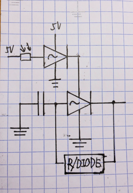
Thanks to the inverter that once again saves us. By applying a inverter in the circuit, we are able to inverse the input and achieve the goal easily–at least I think it must be easy before. With this simple idea, I work out the following schematic
However, this circuite does not work. It is obvious that the inverter is like an open circuit that it takes all voltages away no matter how much resistance the variable resistor has.
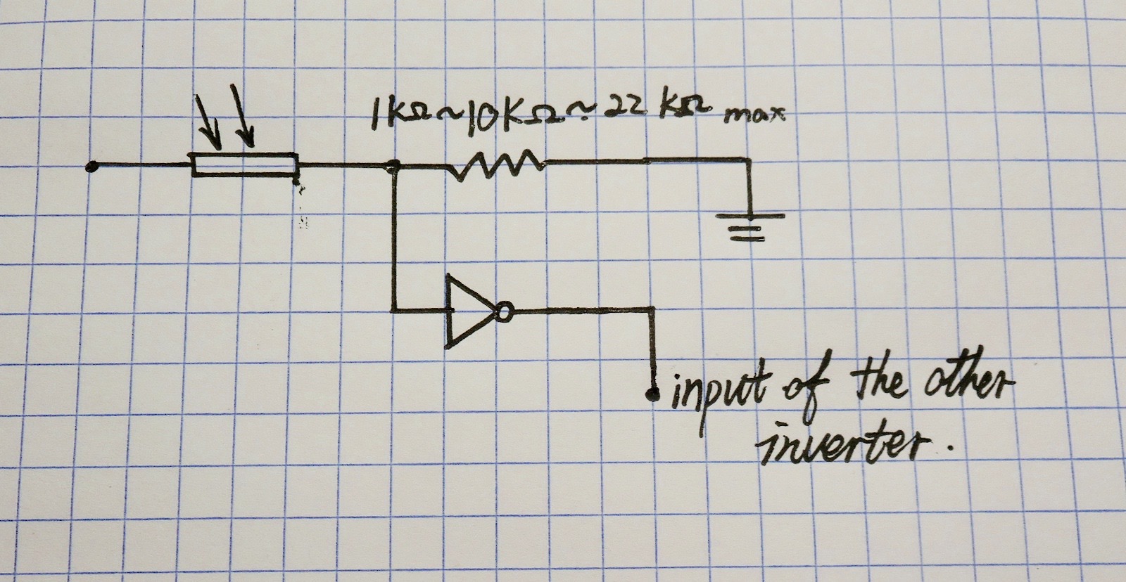
With this failure, we seek other ways to attack the problem. One of them we succeeded in is the usage of voltage divider. The concept is that we use two resistors in series, one is the variable resistor (from 0.5kohm to 34kohm with the variation of brightness of the environment), the other is a normal resistor with the resistance half in the way between 0.5 to 34 kohm–which is about 17 ohm. Then making the inverter connect in parallel with the normal resistor. When there is light, the resistance of the variable resistor must be low, then the voltage across the normal resistor is high, thus giving a high input in the inverter. As the inverter can only give out digital signals (0v or 5v but not other value between them), the light won't be on. On the other hand, then, the light will be powered if the environment is dim.
Here is the schematic of the design
TAs tend to believe that this circuit won't work and I make a real circuit out of this schematic to prove its availability. To make the circuit simple, I did not add the rest of the circuit to make the light flash. Instead, I use a LED and a resistor to test if this circuit works.
And it works pretty well.
We also find a pattern here for the normal resistor we use. In the beginning, we used a 22kohm resistor but it turns out to be insenstive to the light change. Then we decrease the resistance to 10 kohm until 1kohm and we find that the less the resistance of the normal resistor, the more senstive the system is to the darkness. According to this pattern, we will do more experiements empirically: trying day and night in different weathers and different conditions( in tunnel or under a roadlight for examples) in order to determine the resistance of the normal resistor.
Automated switch to detect when the rider is on the bike
By Kausik Venkat and Yupeng Yang
The purpose of this is to create an automatic switch that will detect when the bike is in motion to control the light. The reason for this is at night time, the photosensor would detect the absence of light and turn on but we do not want the light system to be active when the biker is not on the bike.
We have researched on how to make this possible and come up with a few options. We are also trying to make this without the use for an arduino to reduce costs and make it completely analog.
- The first option is a vibration sensor. This vibration sensor will be attached to the wheels of our bike. The vibration sensor will be activated when the bike is moving and detect that the user is moving. If we implement this solution, we are thinking of including a time delay so that when the user stops at a traffic light, his bike light will still be active.
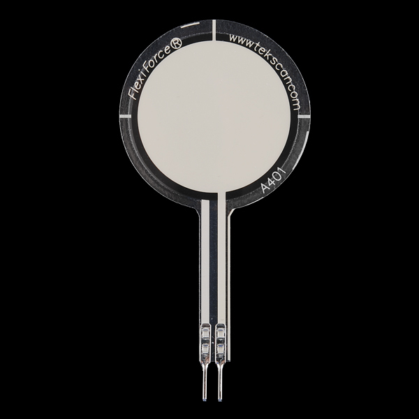
- The second option is a pressure sensor. This pressure sensor will ideally be placed under the bike seat so it will be activated when the rider sits on his bike. This will determine when the rider is riding the bike. We won't need a time delay for this because we assume the rider will be on the bike even when he stops at traffic lights.
- The third option we have considered is an IR sensor. This was suggested to us by one of our TAs. IR sensors work very similarly to touch sensors. They omit a light and detect how much of the light is reflected back. We were thinking of implementing this on the bicycle handles to determine whether there is an user on the bike.
Next week, we are looking to narrow down our choices and then start building the electrical circuit and testing it out (once the parts arrive).


