In this assignment you will write code that transforms a shapeshifting alien path planning problem into a graph search problem. See the Robotics sections of the lectures for background information.
Basic instructions are the same as in MP 1. Specifically, you should be using Python 3.12 with pygame installed, and you will be submitting the code to Gradescope. Your code may import modules that are part of the standard python library, and also numpy and pygame.
For general instructions, see the main MP page and the syllabus.
You will need to adapt your A* code from MP 3/4. Note this assignment shares a template with MP6, so some files will go used until then.
Many animals can change their aspect ratio by extending or bunching up. This allows animals like cats to fit into small places and squeeze through small holes.


Larry the cat, chief mouser at 10 Downing St.
Left is from the BBC, 15 November 2011. Right is from the Daily Mail, 27 June 2012.
You will be moving an alien robot using straight-line paths between waypoints, based on this idea, to reach a goal. Specifically, the robot lives in 2D and has three degrees of freedom:
Notice that the robot cannot rotate. Also, to change from the long vertical form to/from the long horizontal form, the robot must go through the round form, i.e., it cannot go from its vertical oblong shape to its horizontal oblong shape directly. The robot also cannot make both a shape change and position change in the same move. These transitions must be done separately.
The round form is a disk (or a filled circle). The horizontal or vertical long form is a “sausage” shape, defined by a line segment (it’s “spine”) and a distance “d”, i.e., any point within a given distance “d” of the spine between the alien’s head and tail is considered to be within the alien .
For each planning problem you will be given a 2D environment specified by:
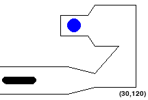
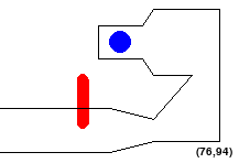
You need to find a shortest path for the alien robot from its starting position to ONE of the goal positions using straight-line paths between waypoints. An example is shown below:
If this image fails to load, try right clicking on the white space above and click “Open Image in New Tab”
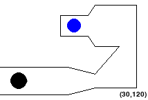
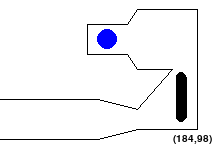
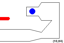
The tricky bit is that the alien may not pass through any of the obstacles. Also, no part of the robot should go outside the workspace. So configurations like the following are NOT allowed:
Accordingly, a straight-line path is valid if and only if it connects waypoints or goals and the alien stays in bounds and does not touch obstacles on that path. Also note that, since we choose waypoints randomly, there may be some waypoints that are too close to the edge or obstacles for particular shapes. To account for this, you will need to remove invalid waypoints before executing your search.
We consider the maze solved once the alien’s centroid is at a goal position, as long as the alien is not violating any constraint (i.e., not out of bounds or touching a wall).
To solve MP5 and MP6, you will go through three main steps, completing only the geometry for MP5:
In order to adapt A* to this problem, we need to understand how searching in the maze can be formulated as searching through a weighted graph.
First, the nodes of the graph will represent points in the state space. In this problem, the state space is a set of tuples (x, y, shape) for all waypoints and goals (x, y) and shapes such that (x, y, shape) is in bounds and doesn’t touch an obstacle.
An edge exists between two nodes if there is a valid straight-line path between their states in the maze. Next, we define the cost, or edge weights:
The objective, then, is to find the lowest cost path to a goal node. You will implement this search in MP6.
The first step is to work out the geometrical details to check moves in the configuration space.
The alien robot has two forms that are represented with geometric shapes:
Form 1 (Ball): A disk with a fixed radius. This entire disk is the alien’s body.
Form 2 (Oblong): An oblong (sausage shape). This is represented as a line segment (spine) with a fixed length and a radius. Any point within the specified radius of the spine belongs to the alien’s body, hence its sausage-like appearance.
We provide a helper class to help you: Alien. Do not modify this class . To solve this MP, you will likely find the following Alien methods to be useful:
alien.py
get_centroid(): Returns the centroid position of the
alien (x,y)get_head_and_tail(): Returns a list with the (x,y)
coordinates of the alien’s head and tail
[(x_head,y_head),(x_tail,y_tail)], which are coincidental if the alien
is in its disk form.get_length(): Returns the length of the line segment of
the current alien shapeget_width(): Returns the radius of the current shape.
In the ball form this is just simply the radius. In the oblong form,
this is half of the width of the oblong, which defines the distance “d”
for the sausage shape.is_circle(): Returns whether the alien is in circle or
oblong form. True if alien is in circle form, False if oblong form.set_alien_pos(pos): Sets the alien’s centroid position
to the specified pos argumentset_alien_shape(shape): transforms the alien to the
passed shapeThe main geometry problem is then to check whether
To do this, you need to implement the following functions:
geometry.py
is_alien_within_window(alien: Alien, window: Tuple[int]):
Determine whether the alien stays within the window.does_alien_touch_wall(alien: Alien, walls: List[Tuple[int]]):
Determine whether the alien touches a walldoes_alien_path_touch_wall(alien: Alien, walls: List[Tuple[int]]:, waypoint: Tuple[int, int]):
Determine whether the alien’s straight-line path from its current
position to the waypoint touches a wall.These functions are easier to implement if you know how to compute (1) distances between a point and a line segment for these functions, as well as (2) distances between two line segments. You will also want to be able to check if a point lies inside a polygon. So you need to implement four additional helper functions in geometry.py for computing these quantities (we recommend they be implemented in the order below):
point_segment_distance(point, segment): Compute the
Euclidean distance from a point to a line segment,
defined as the distance from the point to the closest point on the
segment (not a line!).do_segments_intersect(segment1, segment2): Determine
whether two line segments intersect.segment\_distance(segment1, segment2): Compute the
Euclidean distance between two line segments, defined as the shortest
distance between any pair of points on the two segments.is_point_in_polygon(point, polygon): Determine whether
a point is in a parallelogram.Lecture note “geometry cheat sheet” should be helpful, as well as drawing down and considering some examples. In addition, in robotics, it is commonplace to err on the side of caution - Therefore, If the alien is found to be TANGENT to either the WALLS or the BOUNDARIES it should be considered AN INVALID configuration - i.e. should return True in the collision checking. We have built in some assertions at the bottom of geometry.py to help with basic debugging, which can be executed by:
python3 geometry.py
As mentioned before, once this class is properly implemented, you can also perform visual validation by running:
python3 mp5_6.py --human --map \[MapName\] --config maps/test_config.txt
The file maps/test_config.txt contains several maps. MapName is the name of the one you’d like to run. That is, MapName should be Test1, Test2, Test3, Test4, or NoSolutionMap.
When assessing whether a path is clear, you need to consider the entire path. It’s not sufficient to check whether the alien contacts an obstacle at the start or end of the path.
For checking whether an alien’s PATH touches a wall, there are two cases. The circle case isn’t hard. If you move the center of the circle along a straightline path, it sweeps out something that looks like an elongated alien. So you can do this one by finding the distance between the path and each wall, just like you did with the elongated alien touching a wall.
If the alien is horizontal or vertical, its spine will sweep out a parallelogram as it moves from one position to another. You need to check if that whole parallelogram (including its interior) is free of walls, also that there’s no wall within the robot’s radius of the parallelogram.
To understand all the possible cases, draw some pictures illustrating the ways that a wall (aka line segment) might be located relative to the parallelogram (what the spine of an extended robot touches as it moves between two points). Best if you draw a short wall and a big parallelogram. There’s two, qualitatively different, situations you need to test for. One of them will involve the utility function you wrote about polygons/parallelograms.
Each scene (or problem) is defined in a settings file. We wrote the code to read each settings file for you.
The settings file must specify the alien’s inital position, geometry of the alien in its different configurations, the waypoints, the goals and the edges of the workspace. Here is a sample scene configuration:
  Window : (220, 200)                     # (Width, Height)
  Obstacles : \[
                (0,90,100,90),  # (startx,starty,endx,endy)
                (100,90,140,105),
                (140,105,175,70),
                (175,70,140,70),
                (140,70,130,55),
                (130,55,90,55),
                (90,55,90,25),
                (90,25,130,25),
                (130,25,140,10),
                (140,10,210,10),
                (210,10,210,140),
                (210,140,140,140),
                (140,140,100,150),
                (100,150,0,150)]

  Goals : [(110, 40)]               # (x-coordinate, y-coordinate)
  WayPoints: [  (87, 25),
              (198, 183),
              ...]
  Lengths: [40,0,40]
  Widths: [11,25,11]
StartPoint: [30,120]\['Horizontal Length', 'Ball length (always 0)', 'Vertical Length'\].
The length of the robot is defined by the distance between its head and
tailget\_widthsfunction in the Alien
class.(startx, starty, endx, endy)Here is how the map from this configuration looks without waypoints:
You can play with the maps (stored in config file “maps/test_config.txt”) by manually controlling the robot by executing the following command:
python3 mp5_6.py –config maps/test_config.txt –map Test1 –human
Feel free to modify the config files to do more self tests by adding test maps of your own.
Once the window pops up, you can manipulate the alien using the following keys:
While implementing your geometry.py file, you can also use this mode to manually verify parts of your solution, as the alien should turn red when touching an obstacle or out of bounds, and should turn green when validly completing the course, as shown in the initial figures.
You can get additional help on the parameters for the main MP program by typing python3 mp5_6.py -h into your terminal.
The code you need to get started is in this zip file. You will only have to modify and submit following file:
Do not modify other provided code. It will make your code not runnable.
Please upload geometry.py to gradescope.
Do not submit extra files to gradescope.