| CS440/ECE448 Fall 2018Assignment 2: Configuration Space PlanningDue date: Monday September 30, 11:59pm |
Credits (Fall 2019): Zih-Siou Hung, Devansh Shah
In this assignment you will write code that transforms a 2D planning problem for a robotic arm into a configuration space, and then searches for a path in that space. See Section 25.4 of the textbook and Lecture 7 for background information.
Contents
- General Guidelines
- Problem Statement
- Part0: Map Configuration
- Part1: Geometry
- Part2: Transformation to Maze
- Part3: Searching the Path in Maze
- Extra Credit
- Provided Code Skeleton
General guidelines
Basic instructions are the same as in MP 1. Your code must be in Python 3.6 or 3.7 and will be submitted to gradescope. Your code may import extra modules, but only ones that are part of the standard python library . Extra credit is capped at 10% (so the score for the MP will not exceed 110%).
Two changes from MP 1:
- In addition to the standard python libraries and pygame, you may import numpy.
- The extra credit portion will be submitted separately on gradescope.
For general instructions, see the main MP page and the course policies.
You will need to re-use your bfs code from MP 1.
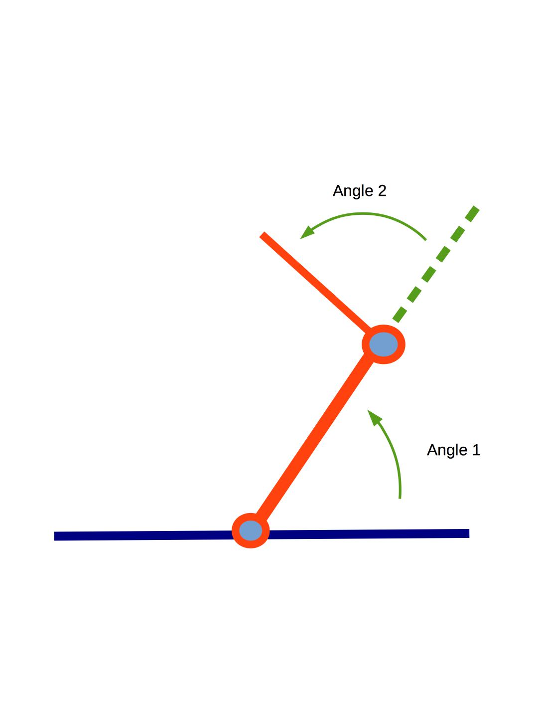
You are given a two-link arm in 2D space as explained in class. This arm has two
links of length \(L_1\) and \(L_2\) respectively.
The arm is free to rotate about
its base that is pivoted on the ground and link-2 can rotate about the joint where it connects
with link-1.
Let's use \(\alpha \)
for the angle
between the link-1 and the ground (equivalent to \(\theta_1\)). Let's use \(\beta \) for
the angle between link-2 and link-1 (equivalent to \(\theta_2\)).
The robot is shown at the top of the page with visualization of \(\theta_1\) and \(\theta_2\). Note that the angles are measured counter-clockwise.
For each planning problem, you will be given:
More details can be found in Map Configuration.
You need to find a shortest path for the robotic arm from its starting
position to the goal so that the tip (open end of the arm) touches or is
inside the goal.
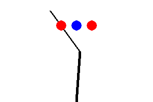
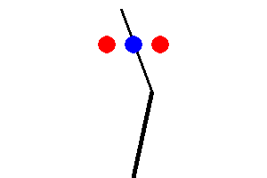
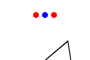
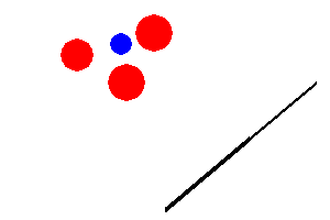
The tricky bit is that the robotic arm may not pass through any of the
circular objects including a goal and an obstacle. Also, any part of the arm
should not get out of the given window.
So configurations like the following are NOT allowed:
You will do your path planning in two steps:
For compatibility with MP 1, you will digitize the angles \(\alpha\)
and \( \beta \) when creating your configuration space map so that the map will
only be an approximation to real life.
Also, the arm is allowed to only change one of \(\alpha\) or \( \beta \) in one step.
Each step will change one of the angles by a fixed number called the angular resolution that is measured in degrees.
The angular resolution will be an
input parameter to your method, so that it can be adjusted for your tests
and for our evaluation of your code.
There is a tradeoff here: finer resolution will allow the arm to get
through smaller gaps between obstacles but it will also slow down your
search.
The window size for the given example map is 300x200 pixel. The arm base is placed at (150, 200).
Note that (0, 0) is the left-top corner and (300, 200) is the right-bottom corner.
There are two arm links. The length of the first arm link is 100 and its initial angle (\(\alpha\)) is 40.
The minimum and maximum angle for this arm link is 20 and 160. The next arm link can be explained in the same manner.
Look carefully at the conventions for \(\alpha\) and \(\beta \) in the
diagram at the top of this page. Both angles are measured counter-clockwise.
\(\alpha\) is relative to the ground and
\(\beta \) is relative to the direction of link-1.
There are three obstacles, each of them is described in tuple (x-coordinate, y-coordinate, radius).
Goals can be described in the same convention. Technically, there can be more than one goal.
However, for simplicity, you can assume that there is only one goal for this MP.
The generated 2D map for above configuration is shown in following:
You can play with the above map with the following command if your geometry functions are correctly implemented:
Once the window pops up, you can rotate the arm using the following keys:
The first problem in geometry is to compute (start, end) position of each arm link for the given \(\alpha\)
and \( \beta \). The base position, initial angle, and length of link-1 is given in configuration, so the end position of link-1 can be computable.
The end position becomes the base position of link-2. Then, the end position of link-2 can be also computable for the given length and \( \beta \).
We kindly provide two helper classes: Arm and ArmLink. One arm can have at least 1 arm link and at most 3 arms links.
You do not have to modify these two classes. To solve MP2, the following Arm methods would be useful:
arm.py
The relationship among arm links are already defined in Arm. What you
need to define is how to compute the end position of the arm link for
the given length and angle. To this end, you may need to implement the
following function:
geometry.py
Once you correctly define the above function, above red colored getEnd() and getArmPos() functions would perform as expected.
The next geometry problem is then to check whether
To do this, you need to implement the following functions:
geometry.py
Once all geometry related functions are implemented, you can check whether they function correctly through manual robotic arm control.
You will get a 'SUCCESS' message when the arm tip touches anywhere of the goal.
The second part of this MP is to transform the generated 2D map to the maze in MP1.
Rows and columns in the maze would match with alpha and beta, joint angles of the robotic arm.
The number of rows and columns of the maze can be decided by 1) degree granularity (angular resolution) and 2) minimum / maximum value of the angle.
The number of positions in the row or column is
\(\frac{\text{maxangle} -\text{minangle}}{\text{granularity}} + 1 \).
For example, if range of alpha is (45, 135) and degree granularity is 2, then the number of rows becomes \( 46 = \frac{135-45}{2}+1\).
When the output of the division is not an integer, round it down.
Once the maze size is determined, then you need to fill the starting point, walls, goals in the maze.
Initial alpha and beta would be the starting point.
To contruct walls and goals, you need to use geometry functions defined in Part 1.
The naive approach is to do bruteforce checking for all pairs of alpha
and beta. Or you can apply some smart short-cut techniques to bypass
unnecessary checking. For example, if the first link already hits an
obstacle, you may not need to check beta for that alpha. Although you
use your own shortcut algorithm, the output maze should look same as
the result of the bruteforce algorithm.
Your main effort for Part 2 would be to implement the following function.
transform.py
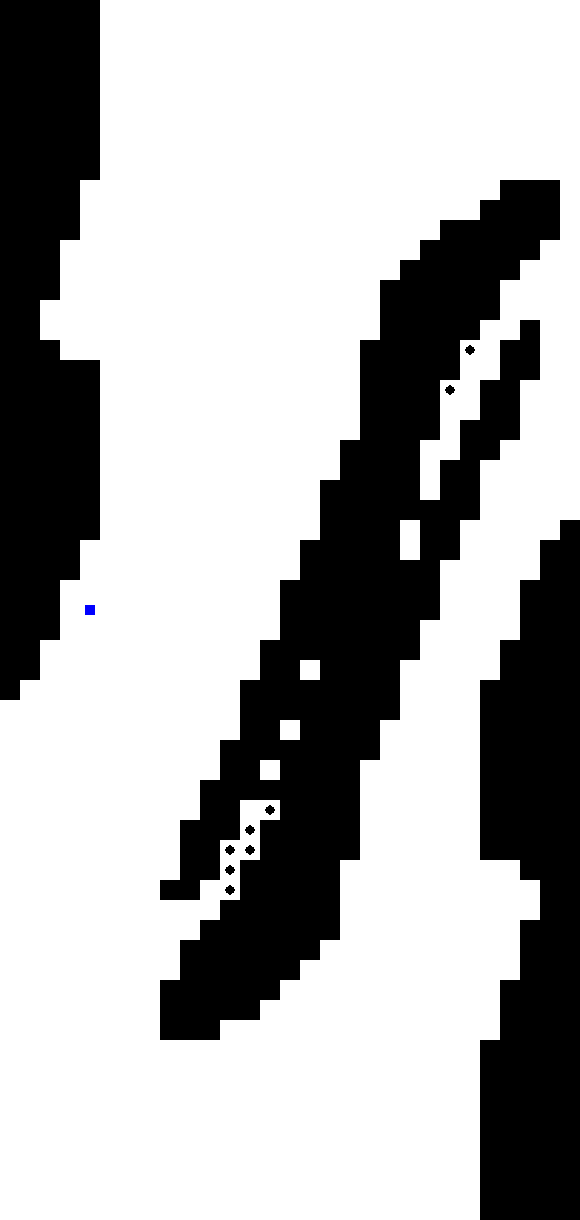
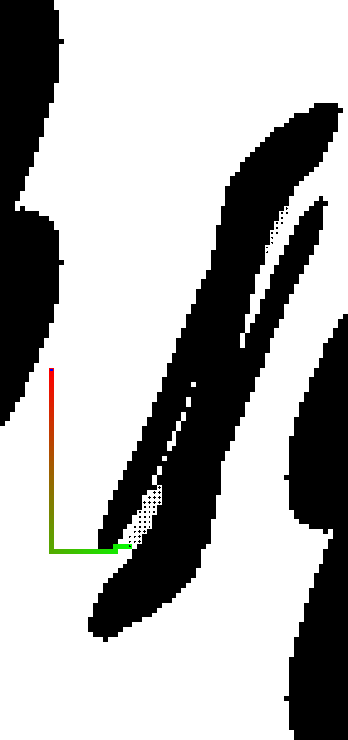
The following images are examples of output maze for Test1 above. The left image has the finer granularity and the right image has the coarser granularity. As you can see, the maze resolution is determined depending on the input granularity. As can be seen, you should be able to handle any level of granularity. Granularity is a natural number for simplicity.
mp2.py does not generate the maze map as above. If you would like to visualize the map, you should run mp2.py to export the maze to a text file, which is an input file of
mp1.py. Then, you can run your mp1.py to create the maze map. That is,
Note that maze.py in MP1 and MP2 is slightly different, so please do not use MP1 maze.py for MP2 and vice versa.
Now we are back to MP1. You can exploit your previous search functions to find the path to exit the maze with minor modifications.
In MP2, you do not have to worry about multiple goals (dots). Your search function should be terminated after your agent reaches any of goals, Otherwise, it would take ages for agents to visit all the goals in the maze.
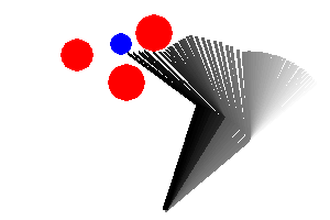
The final state of the robotic arm for Test1 is shown in the left image. You can leave the footprint of the arm rotation in every n move with "--trajectory n" option. Accordingly, the explored shortest path for the maze is described in the right image.
Generalize your computation to robots with one and three links. This means that your
configuration space map will need to be three-dimensional.
We have included a sample problem involving a 3-link (Test1, Test2) robot.
Can your algorithm solve this problem?
The code you need to get started is in
tar file and zip file.
You will only have to modify following files:
Do not modify other provided code. It will make your code not runnable.
To understand how to run the MP, read the provided README.md or
run python3 mp2.py -h into your terminal. The following
command will display a 2D map and let you control the robotic arm manually (q and w for link-1, a and w for link-2, z and x for link-3).
You can also save your output picture using --save-image option. If you want to export your maze to the text file, use --save-maze option.
The following command will run your bfs search method on the maze.
Please upload only search.py, transform.py, geometry.py one by one to gradescope for MP2.
For extra credit, upload search.py, transform.py, geometry.py, and maze.py to MP2_extra.
After submission, gradescope will run preliminary tests to
determine whether or not your submission appears valid. These
preliminary tests are worth 0 points, and are for your information
only. Passing all of these preliminary tests does not guarantee that
your implementations are correct.
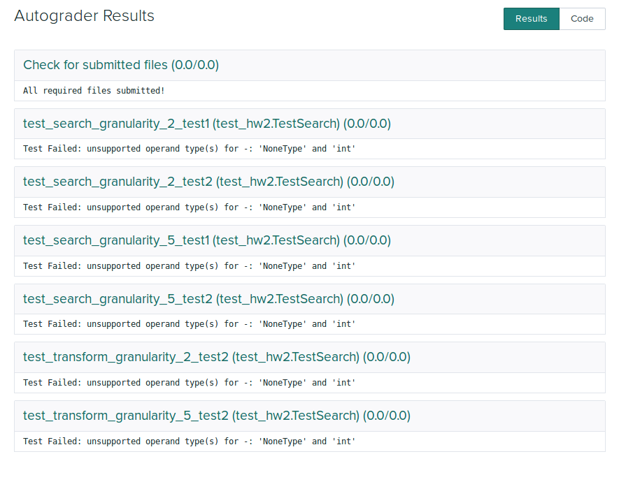
Here's what the autograder outputs if you simply submit the provided skeleton
code:
If you don't see a similar series of test results in a reasonable
amount of time, the autograder has probably crashed (e.g. because
you imported a module that wasn't allowed for this MP) or has gone
into an infinite loop. Fix your code and resubmit. If the
autograder is still running, a resubmission will cause it to stop
work and restart on your new submission.
Problem Statement
Part 0: Map configuration
First of all, you need to understand the 2D space that describes a robotic arm, a goal, and obstacles.
The following example map, named 'Test1', would help you to understand map configuration specifications.
[Test1]
Window    : (300, 200)      # (Width, Height)
ArmBase   : (150, 190)      # (x-coordinate, y-coordinate)
ArmLinks  : [
                (100, 40, (20, 160)),    # (length, initial angle, (min angle, max angle)
                (80, 0, (-150, 150)),
            ]
Obstacles : [
                (70, 50, 15),     # (x-coordinate, y-coordinate, radius)
                (140, 30, 17),
                (115, 75, 17)
            ]
Goals     : [
                (110, 40, 10)      # (x-coordinate, y-coordinate, radius)
            ]
python3 mp2.py --human --map Test1 --config test_config.txt
Part 1: Geometry
The first part of this MP is to work out the geometrical details.
Part 2: Transformation to Maze


python3 mp2.py --map Test1 --config test_config.txt --save-maze [MAZEFILE_PATH]
python3 mp1.py [MAZEFILE_PATH]
Part 3: Searching the path in Maze
Extra Credit
In the geometry section above, rough approximation to decide a contact between the robotic arm and objects will make the maze inaccurate. Can you do a more exact analysis of when the link can contact a circular object?
Provided Code Skeleton
python3 mp2.py --human --map [MAPNAME] --config [CONFIGFILENAME]
python3 mp1.py --method bfs --map [MAZEFILE_PATH]
Tips
Deliverables
This MP will be submitted via gradescope.