| CS440/ECE448 Fall 2018Assignment 2: Configuration Space PlanningDue date: Monday October 1st, 11:55pm |
In this assignment you will write code that transforms a 2D planning problem for a robotic arm into a configuration space, and then searches for a path in that space. See Section 25.4 of the textbook and Lecture 7 for background information.
Contents
- General Guidelines
- Problem Statement
- Part0: Map Configuration
- Part1: Geometry
- Part2: Transformation to Maze
- Part3: Searching the Path in Maze
- Extra Credit Suggestion
- Provided Code Skeleton
- Report Checklist
General guidelines
Basic instructions are the same as in MP 1. To summarize:
- For general instructions, see the main MP page and the course policies.
- We will do some code testing, but it may not be exhaustive.
- You will not get credit for tests, features, or anything that is not been mentioned in your report. Make sure to fully describe your design and your testing.
Your moodle submission should include:
- Your report (formatted pdf).
- A copy of geometry.py, transform.py, and search.py containing all your new code.
- (Groups only) Statement of individual contribution.
Extra credit may be awarded for going beyond expectations or completing the suggestions below. Notice, however, that the score for each MP
is capped at 110%.
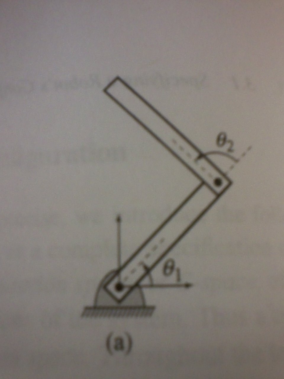
You are given a two-link arm in 2D space as explained in class. This arm has two
links of length \(L_1\) and \(L_2\) respectively.
The arm is free to rotate about
its base that is pivoted on the ground and link-2 can rotate about the joint where it connects
with link-1.
Let's use \(\alpha \)
for the angle
between the link-1 and the ground (equivalent to \(\theta_1\)). Let's use \(\beta \) for
the angle between link-2 and link-1 (equivalent to \(\theta_2\)).
The robot is shown at the top of the page with visualization of \(\theta_1\) and \(\theta_2\). Note that the angles are measured counter-clockwise.
For each planning problem, you will be given:
More details can be found in Map Configuration.
You need to find a shortest path
for the robotic arm from its starting position to the goal so that the open tip of the arm touches or is inside the goal.
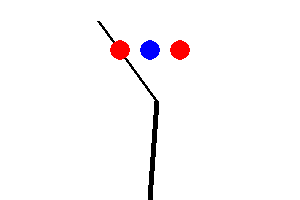
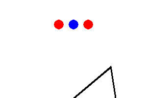
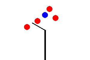
The tricky bit is that the robotic arm may not pass through any of the
circular objects including a goal and an obstacle. Also, any part of the arm
should not get out of the given window.
So configurations like the following are NOT allowed:
You will do your path planning in two steps:
For each example problem, your report should include not only your computed
path but also a picture of the configuration space map (Maze map).
For compatibility with MP 1, you will digitize the angles \(\alpha\)
and \( \beta \) when creating your configuration space map so that the map will
only be an approximation to real life.
Also, the arm is allowed to only change one of \(\alpha\) or \( \beta \) in one step.
Each step will change one of the angles by a fixed number called the angular resolution that is measured in degrees.
The angular resolution will be an
input parameter to your method, so that it can be adjusted for your tests
and for our evaluation of your code.
There is a tradeoff here: finer resolution will allow the arm to get
through smaller gaps between obstacles but it will also slow down your
search.
The window size for the given example map is 300x200 pixel. The arm base is placed at (150, 200).
Note that (0, 0) is the left-top corner and (300, 200) is the right-bottom corner.
There are two arm links. The length of the first arm link is 100 and its initial angle (\(\alpha\)) is 90.
The minimum and maximum angle for this arm link is 0 and 180. The next arm link can be explained in the same manner.
Look carefully at the conventions for \(\alpha\) and \(\beta \) in the
diagram at the top of this page. Both angles are measured counter-clockwise.
\(\alpha\) is relative to the ground and
\(\beta \) is relative to the direction of link-1.
There are four obstacles, each of them is described in tuple (x-coordinate, y-coordinate, radius).
Goals can be described in the same convention. Technically, there can be more than one goal.
However, for simplicity, you can assume that there is only one goal for this MP.
The generated 2D map for above configuration is shown in following:
You can play with the above map with the following command if your geometry functions are correctly implemented:
Once the window pops up, you can rotate the arm using the following keys:
The first problem in geometry is to compute (start, end) position of each arm link for the given \(\alpha\)
and \( \beta \). The base position, initial angle, and length of link-1 is given in configuration, so the end position of link-1 can be computable.
The end position becomes the base position of link-2. Then, the end position of link-2 can be also computable for the given length and \( \beta \).
We kindly provide two helper classes: Arm and ArmLink. One arm can have at least 1 arm link and at most 3 arms links.
You do not have to modify these two classes. To solve MP2, the following Arm methods would be useful:
arm.py
geometry.py
Once you correctly define the above function, above red colored getEnd() and getArmPos() functions would perform as expected.
The next geometry problem is then to check whether
Each bullet in the above matches with each bullet in the below. That is, you need to implement the following functions:
geometry.py
Once all geometry related functions are implemented, you can check whether they function correctly through manual robotic arm control.
You will get a 'SUCCESS' message when the arm tick touches anywhere of the goal.
The second part of this MP is to transform the generated 2D map to the maze in MP1.
Rows and columns in the maze would match with alpha and beta, joint angles of the robotic arm.
The number of rows and columns of the maze can be decided by 1) degree granularity (angular resolution) and 2) minimum / maximum value of the angle.
For example, if range of alpha is (45, 135) and degree granularity is 2, then the number of rows becomes 46 ((135-45)/2+1).
Once the maze size is determined, then you need to fill the starting point, walls, goals in the maze.
Initial alpha and beta would be the starting point.
To contruct walls and goals, you need to use geometry functions defined in Part 1.
The naive approach is to do bruteforce checking for all pairs of alpha and beta.
Or you can apply some smart short-cut techniques to bypass unnecessary checking.
For example, if the first link already hits an obstacle, you may not need to check beta for that alpha.
Although you use your own shortcut algorithm, the output maze should look same as the result of the bruteforce algorithm.
Please describe how you did this in your report.
Your main effort for Part 2 would be to implement the following function.
transform.py
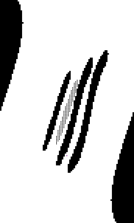
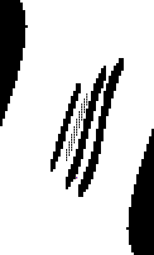
The following images are examples of output maze for BasicMap above. The left image has the finer granularity and the right image has the coarser granularity. As you can see, the maze resolution is determined depending on the input granularity. As can be seen, you should be able to handle any level of granularity. Granularity is a natural number for simplicity.
mp2.py does not generate the maze map as above. Instead, it allows to export the maze to a text file, which is an input file of mp1.py. Then, you can run your mp1.py to create the maze map. That is,
Note that maze.py in MP1 and MP2 is slightly different, so please do not use MP1 maze.py for MP2 and vice versa.
Now we are back to MP1. You can exploit your previous search functions to find the path to exit the maze with minor modifications.
In MP2, you do not have to worry about multiple goals (dots). Your search function should be terminated after your agent reaches any of goals, Otherwise, it would take ages for agents to visit all the goals in the maze.
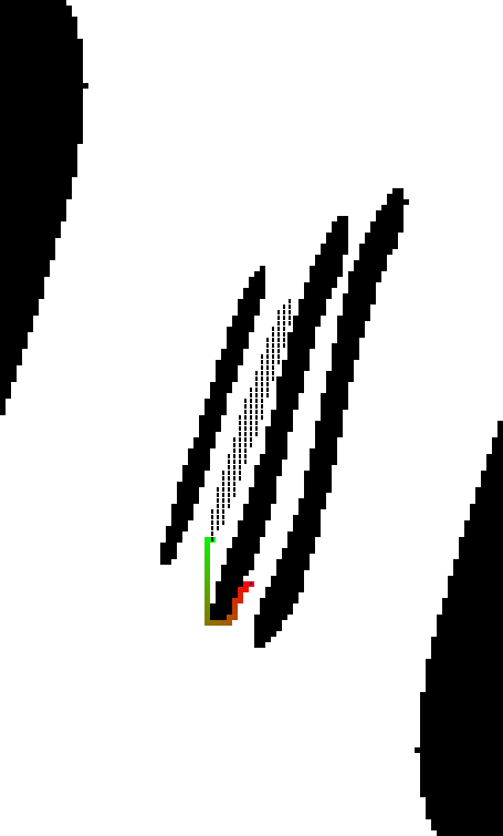
The final state of the robotic arm for BasicMap is shown in the left image. You can leave the footprint of the arm rotation in every n move with "--trajectory n" option. Accordingly, the explored shortest path for the maze is described in the right image.
Generalize your computation to robots with one link and three links. This means that your
configuration space map will need to be one- to three-dimensional.
We have included a sample problem involving a 1-link (Map5) and 3-link (Map6, 7) robot.
Can your algorithm solve this problem?
In the geometry section above, rough approximation to decide a contact between the robotic arm and objects will make the maze inaccurate. Can you do a more exact analysis of when the link can contact a circular object?
Do not modify other provided code. It will make your code not runnable.
To understand how to run the MP, read the provided README.md or
run python3 mp2.py -h into your terminal. The following
command will display a 2D map and let you control the robotic arm manually (q and w for link-1, a and w for link-2, z and x for link-3).
The following command will run your astar search method on the maze.
WARNING: You will not get credit for any solutions that you have obtained,
but not included in your report!
For example, there will be no credit point although your code actually solves 3-D maze problem if you do not describe it in the paper.
Your report must be a formatted pdf document.
Pictures and example outputs
should be incorporated into the document.
Exception: items which are very large or unsuitable for inclusion in a pdf document
(e.g. videos or animated gifs) may be put on the web and a URL included in your report.
For full credit, in addition to the algorithm descriptions, your report should include the following.
Problem Statement

Part 0: Map configuration
First of all, you need to understand the 2D space that describes a robotic arm, a goal, and obstacles.
The following example map, named 'BasicMap', would help you to understand map configuration specifications.
[BasicMap]
Window    : (300, 200)      # (Width, Height)
ArmBase   : (150, 200)      # (x-coordinate, y-coordinate)
ArmLinks  : [
                (100, 90, (0, 180)),    # (length, initial angle, (min angle, max angle)
                (50, 60, (-150, 150)),
            ]
Obstacles : [
                (125, 70, 10),     # (x-coordinate, y-coordinate, radius)
                (90, 90, 10),
                (165, 30, 10),
                (185, 60, 10)
            ]
Goals     : [
                (150, 50, 10)      # (x-coordinate, y-coordinate, radius)
            ]
python3 mp2.py --human --map BasicMap
Part 1: Geometry
The first part of this MP is to work out the geometrical details.
Aforementioned relationship among arm links are already defined in Arm. What you need to define is how to compute the end position of the arm link for the given length and angle. To this end, you may need to implement the following function:
Part 2: Transformation to Maze

python3 mp2.py --map BasicMap --save-maze [MAZEFILE_PATH]
python3 mp1.py [MAZEFILE_PATH]
Part 3: Searching the path in Maze

Extra Credit Suggestions
Provided Code Skeleton
We have provided tar file and zip file. all the code to get you started on your MP. You will only have to modify following files:
python3 mp2.py --human --map [MAPNAME]
python3 mp1.py --method astar --map [MAPNAME]
You can also save your output picture using --save-image option. If you want to export your maze to the text file, use --save-maze option.
Tips
Report Checklist
Your report should briefly describe
your implemented solution and fully answer the questions for every part of the assignment. Your description
should focus on the most "interesting" aspects of your solution, i.e., any non-obvious
implementation choices and parameter settings, and what you have found to be especially
important for getting good performance. Feel free to include pseudocode or figures if
they are needed to clarify your approach. Your report should be self-contained and it should
(ideally) make it possible for us to understand your solution without having to run your source code.
Part 1: Geometry
Describe your geometrical details to achieve reasonable accuracy. Mathmatical fomula (and possibly image) would be good for us to understand.
Part 2: Transformation to Maze
Describe your transformation method. How did you design and implement the function?
What short-cut techniques did you try to save maze creation time?
Please, attach the all generated maze map in config.txt.
What angle resolution did you use for the maps? Why did you make that choice?
Were there any sample problems that you couldn't solve in config.txt? If so, explain why.
Part 3: Searching the path in Maze
Please attach the final state of the robotic arm with "--trajectory 1" for all maps in config.txt.
Please attach the explored path for 2D maze maps using mp1.py.
Extra credit:
We reserve the right to give bonus points for any challenging or creative solutions that you implement.
This includes, but is not restricted to, the extra credit suggestion given above.