Table of Contents
In this programming assignment you will implement the key parts of the fixed functionality of a 2020s-era GPU.
You may solve this assignments in any language you wish, and will write a program that takes a text file in and produces a PNG file, like you did for the associated warmup exercise.
This assignment is split into a required part and a menu of optional parts. For full credit, do all of the required part and 50 points of optional parts. Excess optional points carry over to other assignments’ optional parts, so if you do 100 points of optional on this assignment you can skip the optional parts on another assignment altogether. If you end the term with excess optional points, a small percentage of the excess will considered extra credit, as explained on the syllabus.
Reference input and output files are included below; the full set can be downloaded as mp1files.zip. Do not upload these files as part of your submission: the grading server will supply them instead.
We also have some tips if this is your first open-ended project.
This assignment, like all other assignments, is governed by the common components of MPs.
1 Required
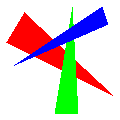
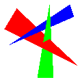
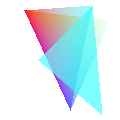
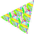
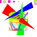
You must implement the following keywords, generating the example
images below from the text files they link to. However, you probably
want to develop your solution in stages: first plot the
xyzw points like you did for the warmup to make sure you
have the w and viewport handling
working (they should appear at the vertices of the triangles in the
reference images); once they are properly positioned and colored, start
working on tri.
pngwidth height filename- same as the warmup
xyzwx y z w-
Add a point with the given homogeneous coordinates (x,y,z,w) to the list of vertices. Also add any per-vertex state, such as
rgb, to the vertex.Most other commands will refer to earlier vertices in a one-indexed way: 1 is the first vertex listed, −1 the most recent one listed. So, for example, in the following input file

png 20 30 mp1indexing.png
xyzw   1  3.5  3 4
xyzw  -1 -2   -3 4
rgb 0 0 0
xyzw   2  0    0 2
tri 1 -1 2
xyzw  -1  0.5  0 1
tri 1 -2 -1
the first
trihas vertices (1,3.5,3,4), (-1,-2,-3,4), and (2,0,0,2); the secondtrihas vertices (1,3.5,3,4), (2,0,0,2), and (-1,0.5,0,1).Vertex indices will always refer to vertices earlier in the file.
For the required part of this assignment, you may assume that w is positive and greater in absolute magnitude than the largest of x, y, and z.
Divide by w and apply a viewport transformation during rendering; thus a vertex given as
png\text{width} \text{height}filename
xyzwx y z wis located at pixel coordinate \left( \left(\dfrac{x}{w}+1\right)\dfrac{\text{width}}{2} , \left(\dfrac{y}{w}+1\right)\dfrac{\text{height}}{2} \right)
Vertex coordinates may be decimal numbers like
10.23both before and after the w and viewport operations.Unless you implement
depth, the z coordinates are irrelevant and can be ignored.We provide some numbers for this example file if you want to check your work.
For the example file here, after dividing by w and perfoming the viewport transformation, the vertices become (12.5,28.125), (20,15), and (7.5,7.5) for the first triangle and (12.5,28.125), (20,15), and (0,22.5) for the second triangle.
For the first triangle:
- The smallest-y scanline has y=8 and fills between 7.621… (rgb all 255) and 8.333… (rgb all 238) in x.
- The y=9 scannline fills between 7.863… (rgb 255) and 10 (rgb 204).
- The y=10 scanline fills between 8.106… (rgb 255) and 11.666… (rgb 170).
- The first scanline after passing the middle vertex has y=15 and fills between 9.318… (rgb 255) and 20 (rgb 0).
- The y=16 scanline fills between 9.560… (rgb 255) and 19.428… (rgb 19.428…).
rgbr g b-
 Change the
 current color
to the given RGB color value. RGB colors are given in 0…255 color space, just as they were in the warmup.Every time a vertex is created, (e.g. by
xyzw), assign it the current color.If no
rgbcommands have been encountered, use the current color of 255,255,255. trii_1 i_2 i_3-
 Fill a triangle between the given vertices, linearly interpolating the
vertex colors as you go.
Fill a triangle between the given vertices, linearly interpolating the
vertex colors as you go.Use a DDA-based scanline algorithm1: DDA step in y along the edges, then DDA step in x between these points.2
Fill a vertex if its coordinates are any of the following:
- inside the triangle (e.g., pixel (3, 4) is inside (2.9, 4), (3.1, 4.1), (3.1, 3.9))
- on the left (small x) edge of the triangle
- on a perfectly horizontal top (small y) edge
Do not fill it otherwise.
Our input files may include vertices on the very edge of the viewport. After numerical error introduced by division by w, it is possible that may result in DDA creating a pixel that is outside the viewport. You code should ignore any such out-of-view pixels.
2 Optional
2.1 Full-scene adjustments
If these keywords appear, they will appear after png and
before any keyword not in this section.
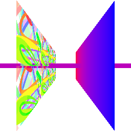
depth(15 points)-
 If this keyword appears enable a depth buffer: store a depth value,
initialized to 1, with every pixel; when drawing, only update the pixel
if the interpolated \frac{z}{w} is less
than the stored depth value (but \ge
-1).
If this keyword appears enable a depth buffer: store a depth value,
initialized to 1, with every pixel; when drawing, only update the pixel
if the interpolated \frac{z}{w} is less
than the stored depth value (but \ge
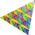
-1).We have a visualization of depth values you can use to check your work
 Depth
buffers require both an accurate depth at each pixel and correct
conditional logic to track what’s happening, which can make debugging
them tricky. In this image I took the depth buffer (which is between
-1 and 1), clamped any negative values to 0,
multiplied by 255, and used the result as the R, G, and B of each pixel.
If you do the same and don’t see something with this general form then
it’s the depth interpolation rather than the conditional logic that
needs fixing.
Depth
buffers require both an accurate depth at each pixel and correct
conditional logic to track what’s happening, which can make debugging
them tricky. In this image I took the depth buffer (which is between
-1 and 1), clamped any negative values to 0,
multiplied by 255, and used the result as the R, G, and B of each pixel.
If you do the same and don’t see something with this general form then
it’s the depth interpolation rather than the conditional logic that
needs fixing.
sRGB(5 points)-
 If this keyword appears, convert colors (but not alpha) from sRGB to
linear color space before interpolating and convert back to sRGB after
interpolating.
If this keyword appears, convert colors (but not alpha) from sRGB to
linear color space before interpolating and convert back to sRGB after
interpolating.The input file’s colors are given already gamma-corrected, and the image file needs gamma-corrected colors. Thus, you’ll need two conversions, one when reading colors from the input file and one when writing colors to the image file.
hyp(10 points; requiressRGBanddepth)-
 If this keyword appears, perform perspective-correct (also called
hyperbolic
) interpolation instead of linear interpolation of depth, color, etc.This keyword will only appear after the
sRGBkeyword. frustum(10 points)-
 Perform frustum clipping on each primitive prior to rendering.
Scenes with
frustummay use zero and negative w values. They will not use the point (0,0,0,0).3See the rasterization page for what the six clipping planes for frustum clipping are.
fsaalevel (10 points; requiressRGBandrgba)-


 If this keyword appears, render with a viewport level times
larger than given in the
If this keyword appears, render with a viewport level times
larger than given in the pngline and then average level×level blocks of pixels to get each pixel of the output image.Perform the averaging before conversion from linear to
sRGB.Weight colors during the averaging based on their alpha values. Unfilled pixels have an alpha of 0, and thus do not contribute to the final
rgb(but do contribute to the final alpha).This keyword will only appear after the
sRGBkeyword. We will only test with level being a small positive integer. cull(5 points)-
 If this keyword appears, only draw triangles if their vertices would
appear in counter-clockwise order on the screen. Otherwise simply ignore
them.
If this keyword appears, only draw triangles if their vertices would
appear in counter-clockwise order on the screen. Otherwise simply ignore
them.The easiest way to find what is clockwise and what is not is to compute two edge vectors of the triangle, take their cross product, and check the sign of the resulting vector’s z coordinate.
decals(10 points; requires textures)-
 If this the keyword appears in the input file, alpha-blend textures on
top of the underlying object color (interpolated as with
If this the keyword appears in the input file, alpha-blend textures on
top of the underlying object color (interpolated as with
tri): transparent parts of the texture should show the underlying object color.If
decalshas not appeared in the input file, just use textures’ RGB values, not the underlying object color, ignoring alpha. clipplanep_1 p_2 p_3 p_4 (5 points)-
 Clip triangles before drawing them. Clipping a triangle along one plane
might turn it into two triangles (by clipping off a corner).
Clip triangles before drawing them. Clipping a triangle along one plane
might turn it into two triangles (by clipping off a corner).Points that satisfy (p_1, p_2, p_3, p_4) \cdot (x, y, z, w) >= 0 should be kept. Apply this to the vertices of a triangle after the Model/View transformations and before the Projection transformations.
Unlike the other keywords in this full-scene adjustments section,
clipplanemay appear multiple times in a single file.
2.2 Additional drawing tools
rgbared green blue alpha (10 points; requiressRGB)-
 Allow colors to be given with an alpha channel, representing opacity
between 0 and 1. Colors given with
Allow colors to be given with an alpha channel, representing opacity
between 0 and 1. Colors given with rgbhave an alpha of 1. Use theover
operator when blending.Note that red, green, and blue are integers between 0 and 255; while alpha is a float between 0 and 1. This is also how standards such as CSS represent these colors.
Our blending description has two formulae: one for premultiplied alpha and one not. Almost all PNG libraries assume they will be given non-premultiplied alpha.
This keyword will only appear after the
sRGBkeyword.Debugging
rgbacan be difficult. We have a menu of common errors that might be helpful. - Textures (15 points; requires
hypandrgba) -
 This is a combination of three commands:
texcoords t-
adds a texture coordinate to all subsequent vertices (similar to the way
colordoes withtrig). Iftexcoordhas not occurred prior to an vertex being specified, use (0, 0) for that vertex’s texture coordinate. texturefilename.png-
adds a texture image to be used in subsequent drawing commands.
The example images on this page use splat2.png as the texture image. We will test your program with other images and other image sizes too. Notably, any of the images created by running your program should work too.
triti_1 i_2 i_3-
draw a texture-mapped triangle. Interpolate the (s, t) texture coordinates to each fragment; the color of each fragment is then the color from the texture at the texel closest to (s w, t h) where the texture is w \times h texels in size.
Texture coordinates should wrap; that is, treat -1.3, -0.3, 0.7, 1.7, etc, as all mapping to the same texel.
You may assume that
tritwill never be called withouttexturebeing called earlier in the file.
pointpointsize i (5 points; requiresdepth)-
 Fill all pixels in a pointsize-pixel-wide square centered on
vertex i. Use the color of the
vertex.
Fill all pixels in a pointsize-pixel-wide square centered on
vertex i. Use the color of the
vertex.All fragments of the resulting square should use the same color and z.
billboardpointsize i (10 points; requirestextureandpoint)-
 Like
Like point, except that each resulting pixel is given a texture coordinate based on where it appears in the resulting square, with (0,0) at the top-left corner and (1,1) at the bottom-right corner. Pixel colors are picked as pertrit. Pixel alphas are taken directly from the texture: vertex color is ignored.
linei_1 i_2 (10 points)-
 Draw an 8-connect line between the two given vertices by DDA-stepping in
whichever direction (x or y) has a larger screen-space separation, then
rounding the other axis to the nearest pixel.
Draw an 8-connect line between the two given vertices by DDA-stepping in
whichever direction (x or y) has a larger screen-space separation, then
rounding the other axis to the nearest pixel.
wulinei_1 i_2 (10 points; requireslineandrgba)-
 Draw a Wu-style
antialiased line between the two given vertices by DDA-stepping in
whichever direction (x or y) has a larger screen-space separation, then
filling the two nearest pixels to each point found along the line with
transparency based on the interpolated distance from the pixel center.
Draw a Wu-style
antialiased line between the two given vertices by DDA-stepping in
whichever direction (x or y) has a larger screen-space separation, then
filling the two nearest pixels to each point found along the line with
transparency based on the interpolated distance from the pixel center.
3 Submission
Submit your source code, Makefile, and implemented.txt
to the submission
site. You may zip or tar them up or just Ctrl+Click to select
several files at once during upload. Remember to include the required
files in your implemented.txt:
mp1indexing.txt
mp1req1.txt
mp1req2.txt
After you submit the server will run some tests and post images if
they are created. This generally takes 15–30 minutes. When it’s done
you’ll see a feedback available
message and any images the server
as able to generate from your code..
The server does not check if you images are correct or not; that’s done by humans. You can see how we compare images in the warmup. As a guideline,
-fuzz 1%is always OK (it represents just basic rounding error in color computations);-fuzz 2%is OK if there are many color conversion steps (as e.g. whensRGBandrgbaare both used).- pixel boundaries should be exact, with just a few single-pixel exceptions where numerical error might accumulate differently for different implementations.